


Moreover, strong changes in the material properties caused by temperature treatment, such as a reduction of mechanical strength due to significant changes in the microstructure should be avoided within the operation temperatures. And finally, the maximum operation temperature should be low in relation to the melting temperature of the respective material, so that damage by material creeping is minimized.
The majority of existing modules is characterized by standard joining technologies such as aluminum wire bonding and soft soldering. They suffer from low inherent mechanical strength and low melting temperatures resulting in a limited reliability at operation temperatures excceding 150°C. Figure 1 depicts the novel joining technology .XT used in the Prime-PACK module with IGBT5.


One method to increase the reliability of the top-side interconnects is to replace aluminum by copper wire-bond material. Because of its much higher yield and tensile strength combined with a lower CTE, the amount of plastic deformation for a given temperature cycle is significantly reduced compared to aluminum.
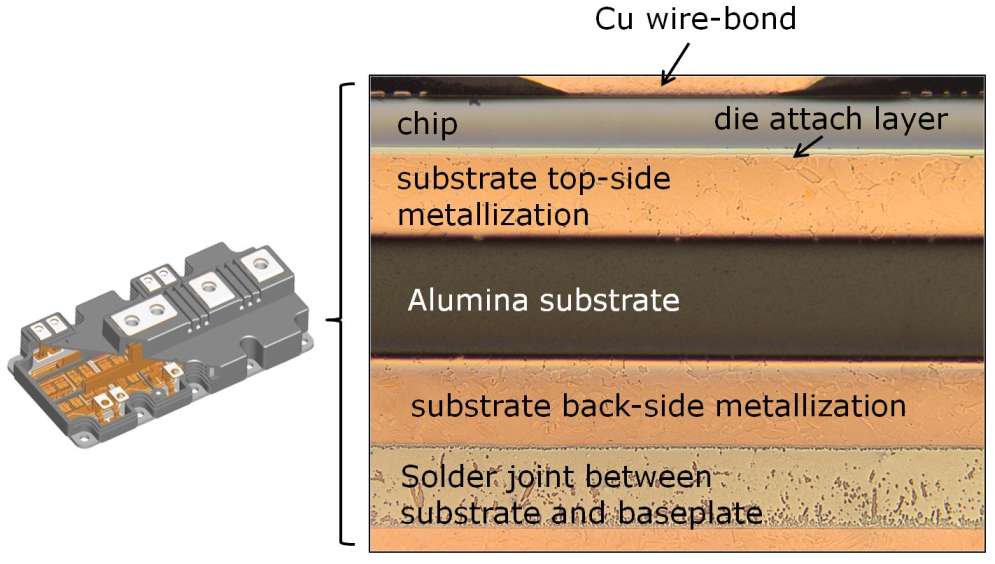
Equally important for the module´s lifetime are novel die-attach technologies such as sintering using silver particles. Improved mechanical properties, with respect to soft solders, are also obtained for sintered Ag die attach layers. This is predominantly a result of the high melting point and the higher mechanical strength of the material.
To enhance the power terminals´ connections as well, ultrasonic welding (US) is implemented. The joint between DCB and BP is upgraded utilizing an advanced solder technology. However, compared to the other interconnect materials, a higher plastic deformation during temperature cycling and creeping fatigue cannot be excluded for the substrate-to-baseplate solder.
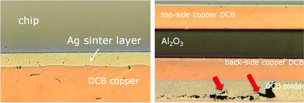
The failure mechanisms in power modules employing improved wire bond technologies, sintering as die attach and the improved solder between substrate and baseplate were investigated in detail, they are displayed in figure 2. The degradation of the substrate-to-baseplate solder has been identified as the most prominent failure mode which is effecting lifetime.