


What is Temperature Coefficient of Resistance?
Temperature coefficient of resistance (TCR) is the calculation of a relative change of resistance per degree of temperature change. It is measured in ppm/°C (1 ppm = 0.0001%) and is defined as: TCR = (R2– R1)/ R1 (T2– T1). For high-precision resistors, this specification is typically expressed in parts per million (ppm) per degrees Celsius, with reference to normal room temperature, typically +25°C.


Despite the importance of this specification, individual resistor manufacturers use different methods for defining TCR on their published datasheets. In most cases, this definition does not provide enough information to enable an end user to accurately predict the influence of temperature changes on the resistance value. Where such published TCR variances are of concern, of course, is in their potential to create measurement uncertainty. Particularly, in applications where high-precision resistor performance and temperature stability are absolute requirements. This uncertainty is created when there is insufficient confidence that a TCR specification has been calculated with enough data to allow for the accurate prediction of the true impact of temperature change on resistor performance.

For example, some manufacturers may opt to list TCR as ±5 ppm/°C or ±10 ppm/°C, without reference to temperature range. Others may specify TCR as ±5 ppm/°C from +25°C to +125°C, yet omit data regarding other temperature ranges. In high-precision devices, such as the Bulk Metal® Foil resistors manufactured by Vishay Foil Resistors, published TCR specifications include nominal typical curves, normally from –55°C to +125°C. Those curves define nominal “cold” (–55°C to +25°C) and “hot” (+25°C to +125°C) chord slopes. Their datasheets typically specify the maximum spread for each slope (e.g., ±0.2 ppm/°C and ±1.8 ppm/°C). In the case of a Bulk Metal Foil resistor, a default TCR interpretation of ±5 ppm/°C, for example, would mean that –at any point across the working temperature range– the resistance would not change more than +5 ppm/°C.
The Vishay Foil Resistors brand of Vishay Precision Group, Inc. (VPG) are longtime global industry experts in the design, development, and manufacture of reliable high-precision Bulk Metal Foil resistors and power current sensors for a diverse array of applications. Hundreds of standard model configurations are derived from one of the industry’s most extensive portfolios of customer-selectable housings, materials, substrates, and metal foil grade combinations. Advanced manufacturing techniques ensure that resistor designs are performance-optimized for consistent operation to published specifications throughout their useful service life. All VPG high-precision Bulk Metal Foil resistors feature some of the industry’s most favorable TCR specifications, uniformly calculated per stringent industry best practices. This ensures their reliability across all resistance and operating temperature ranges.
This paper shall examine TCR and its “best practice” interpretations, as recommended from VPG’s own vast experience in high-precision resistors. Overall goals shall be to better understand precision resistor performance, as it relates to temperature; to illustrate nuances among and between published TCR specifications, depending upon technology type and a manufacturer’s own chosen calculation method; and to offer further insights for TCR data utilization, as a means of ensuring that a specified precision resistor can reliably perform within its intended application.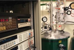
The Relationship Between Temperature and High-Precision Resistor Performance
The impact of temperature upon resistor performance is reflected, both internally, in terms of its effects on component operation; and externally, in terms of resistor behavior within the installation environment. Inherent to resistor design is the concept that, as electrical current flows through a resistor, it generates a certain amount of heat. This is a phenomenon known as the Joule effect. The thermal response created by the Joule effect then induces relative mechanical changes, or stresses, within the resistor. These stresses are caused by differential thermal expansions in the resistor materials of construction, amounts of which can vary, based on the materials themselves. Ambient temperatures within the installation environment can similarly influence resistor response, in terms of generating heat which can potentially affect resistor performance.
An optimal design is therefore one which minimizes high-precision resistor susceptibility to external and internal stresses during different usages and power loads, without sacrificing performance and reliability. In Bulk Metal Foil resistive technology, this goal is achieved by the creation of a precise thermo-mechanical balance between generated heat, materials of construction, and associated manufacturing processes. Through careful design, the need to compensate for the effects of heat and stress during operation can therefore be virtually eliminated, further increasing performance stability. In recognition of the important relationship between temperature and high-precision resistor performance, the R&D team at Vishay Foil Resistors ensures that its full ultra-high precision resistor portfolio is designed in this manner.
For example, during the development of a Bulk Metal Foil element, a proprietary cold-rolled foil material is bonded onto a ceramic substance. That material is photoetched into a resistive pattern, without introducing mechanical stresses onto the material. Following this process, high-precision resistors are laser-adjusted to a specified resistance value and tolerance. Because the resistive material is neither drawn, wound, nor mechanically stressed during the manufacturing process, the high-precision Bulk Metal Foil resistor can maintain its complete intended design characteristics, and therefore full performance reliability, including TCR.
 In contrast, other common resistor manufacturing methods, such as wire winding, thin-film sputtering, or thick-film glazing, have an inherently greater likelihood for the introduction of mechanical stresses, and therefore greater potential for thermo-mechanical imbalance. End users are therefore recommended to pay close attention to rated temperature specifications, to ensure that a resistor is operating according to published specifications. By adhering closely to these values, the end-user can be assured of continued resistor reliability, regardless of the manufacturing process. When a resistor is operating above rated temperatures, it can fail to function, or otherwise incur damage which directly compromises accuracy. Should such resistor over-temperature conditions persist over an extended timeframe, individual resistance values may permanently change, leading to complete circuit malfunction. While manufacturers do routinely design products with a certain added margin of acceptable temperature limits beyond published specifications, such leeway can vary significantly by manufacturer.
Interpreting TCR, Chord Slopes and Change Rate Analysis Specifications
Despite differences in designs and associated manufacturing processes, TCR remains one of the most commonly accepted resistor performance stability indicators. TCR is imperative for predicting resistor sensitivity to ambient temperature variations, as well as anticipated component behavior at both low- and high operating temperatures. As a result, the TCR of Bulk Metal Foil resistors takes into consideration extreme theoretical conditions within individual specification limits. In contrast, with other technologies such as thin film, manufacturers typically choose to present TCR in a relatively narrow temperature range, with less emphasis or consideration on extreme temperature effects.
In addition to its previously noted definition, TCR may be further defined as a resistance change between two temperatures, divided by the temperature difference (chord slope), or TCR = (ΔR/R)/ΔT. It is common practice to define cold chord slope from –55°C to +25°C, and hot chord slope from +25°C to +125°C (in this case ΔThot = 125 – 25 = +100°C). However, any other temperature interval (ΔT) may be defined as well. To define the rate of change in resistance at any temperature on that curve, TCR is calculated mathematically when ΔT becomes infinitely small (ΔT→0):
TCR(ΔT→0) = (dR/R)/ dT
It is well-known that the change in resistance vs. temperature in NiCr resistors is not linear, and instead normally follows a parabolic pattern. Mathematically, this function can be described by:
Y = aX2 + bX + c where: Y = ΔR/R (normally expressed in ppm)
X = T (Temperature in °C).
In this case, for any temperature T, Y will express the value of the change in resistance ΔR/R from the nominal value (at +25°C) in ppm. In other words, for the function Y, this will be expressed by the derivative function Y′. This function defines the slope (TCR) of a line tangent to the parabola and indicates how TCR is changing. For the above parabola function:
Y′= 2aX + b (Y′ is expressed in ppm/°C)
For simplicity, one can also use the fact that a chord slope equals the tangent midpoint value of the relevant temperature range. For example, the value of the hot slope (+25°C to +125°C) equals the tangent value (Y′) at the midpoint, T = +75°C.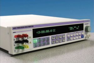
It is a common practice for thin-film resistor manufacturers to target best hot slope while keeping cold slope within the specified limit. A study conducted to compare and analyze Bulk Metal Foil and thin-film precision resistor TCR, using the change rate calculation method, has shown that the change in resistance due to temperature can be significantly larger than specified TCR limits. This comparison is based on the testing of two groups of different precision thin-film NiCr resistors, each from different manufacturers, each specifying a TCR of 5 ppm/°C. Results of this study demonstrated that the maximum change in resistance (TCR) due to temperature changes across the temperature axis from -55°C to +125°C will vary in Bulk Metal Foil resistors from -2.17 ppm/°C to +2.2 ppm/°C, for a total of less than 4.37 ppm/°C. For the same temperature range, the TCR of the thin-film resistor sample from manufacturer A will vary from -3.6 ppm/°C to +7.2 ppm/°C, for a total of nearly 11 ppm/°C; and from manufacturer B, from -9.1 ppm/°C to +4.99 ppm/°C, for a total of 14 ppm/°C. In other words, precision thin-film resistors may exhibit a TCR that is much higher than the specified limits of a manufacturer’s datasheet.
 It is important to emphasize that the TCR of a Bulk Metal Foil resistor is achieved by matching two opposing effects of the inherent increase in resistance due to temperature increase vs. the compression-related decrease in resistance, due to that same temperature increase. These two effects occur simultaneously, resulting in an unusually low, predictable, repeatable, and controllable TCR specification. As a result, Bulk Metal Foil resistors achieve intrinsic maximum stability and near‐zero TCR, a specification which is not reliant on screening or other artificial means for achieving uniform high-precision resistor performance and temperature stability. This stringent TCR calculation method, from the VPG experience, is employed to ensure high-precision resistor reliability across full resistance values and operating temperature ranges.
The Benefits of Low TCR in High-Precision Resistor Applications
Illustrations of the benefits of low TCR may be found within thousands of successful applications. For purposes of this paper, we’ll review three application examples where low TCR offers certain performance advantages.
Precision Instrumentation
Transmille, a leading UK manufacturer of high-accuracy digital multimeters, was seeking a resistor component for a new series of 8.5- and 7.5-digit units. To achieve necessary 8.5-digit accuracy, the specified resistor needed to offer extremely low TCR, high-precision, repeatability, low thermal EMF, low noise, long-term stability and minimal harmonic distortion. As the multimeter was based on an analog circuit design, the resistor needed to have minimal drift from initial values when operating above room temperatures. The customer selected a VPG Bulk Metal Foil resistor, due to its low TCR specification of <1 ppm/°C maximum at +20°C. In addition to extremely low TCR, the resistor offered a low PCR of 5 ppm at rated power; load-life stability of ±0.005% at +70 °C for 2000 hours, or ±0.015% for 10,000 hours; a thermal EMF of <0.05 μV/°C; and non-measurable noise.
The extremely low TCR of the Bulk Metal Foil resistor allowed Transmille to introduce a new digital multimeter to market which could offer both industry best-in-class performance and necessary 8.5-digit accuracy. The resistor offered exceptional stability under maximum allowable drift, over thousands of hours of field service, even under harsh conditions. The user was further able to achieve this level of resistor performance rather cost-effectively. This allowed Transmille to introduce a new high-performance digital multimeter to market at a highly competitive price point.
Metrology Secondary Reference
In another example, VSL, the National Metrology Institute (NMI) of the Netherlands, approached VPG for a high-precision resistor solution, as a secondary reference standard in its quantum Hall resistance (QHR) experiments. QHR is the globally recognized primary quantum resistance standard, with values of around 12.9 kΩ and 6.45 kΩ. To serve as an adequate secondary reference standard, VSL needed a cost-effective, high-precision resistor, the values of which needed to closely match those of the primary QHR standard, yet offer a well-defined four-terminal configuration, low noise, low TCR and no RH effect, along with excellent long-term stability.
Based upon the low TCR offered by VPG, VSL selected one of the company’s ultra-high precision resistors. The chosen resistor integrated 11 elements into a single housing, allowing for lower TCR and longer-term drift than could be achieved via a single resistive element. The device offered the necessary terminal connections, hermetic sealing for humidity protection, and oil fill, further ensuring that resistance values would remain largely unaffected by sudden temperature changes. The units were then tested for TCR value confirmations vis-à-vis the published VPG specification. For this purpose, the resistor was subsequently mounted within an enclosure thermostated at 29.00 ± 0.02°C, for further reduction of TCR effects, then measured against the primary QHR over a more than five-year period. Results of the five-year study showed that the actual long-term TCR of the two Bulk Metal Foil resistive elements were less than 0.5 ppm/°C over a temperature range of +18 °C to +28 °C, with a (very) small second-order temperature coefficient Beta. This was well below the initial published 2 ppm/°C specification (over -55 °C to +125 °C), and proved the VPG resistors to be a reliable secondary QHR reference standard. Here, published TCR served as an added benefit, in terms of its empirically proven capability to exceed published specifications under long-term use.
Diode Laser Current Drivers
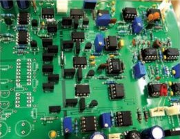
In another example, low-cost and easy-to-use diode lasers are a virtual measurement staple in experimental atomic physics. For a diode laser to maintain its frequency, output power, current and temperature, careful regulation of parameters is required. To best manage costs, the Physics Department at California State University looked to construct its own low-cost, low-noise current source for use with its in-laboratory diode lasers. To generate a suitably stable laser stream, the current sense resistor needed to be resistant to both internal and external temperature drifts, have a high-power rating, and a low thermal EMF. The most critical element of the current driver is the sub-circuit, responsible for current regulation since laser stability must not exceed overall sense resistor stability. In this application, the use of traditional commercial current controllers was too cost-prohibitive. The viable resistor solution therefore needed to be both low-cost and high-precision.
By using a high-precision Bulk Metal Foil resistor with a low TCR of 2 ppm/°C typical (–55°C to +125°C, +25°C ref.), tolerance of 0.01% and a 10 W power rating, the end user could integrate a regulated voltage within its sub-circuit, and yet still control the amount of current emitting from the laser current driver. The latter was achieved by tuning the driver to a set voltage on an adjustable voltage regulator. This preset total resistance value ensured that the voltage drop was large enough for accurate current regulation, though small enough as not to influence regulated supply voltage. Here, the specific combination of long-term stability and low TCR made the Bulk Metal Foil resistor an optimal solution within a low-cost, high-precision application. The solution proved to be viable, as the user was assured of TCR specification accuracy.
The “True” Value of TCR in High-Precision Resistor Selection
For engineers selecting high-precision resistors, TCR specifications can help them to better predict reversible shifts in component resistance from an ohmic value within the application, both under intended operating temperatures and within the installation environment. Such data offer insights into key longer-term resistor performance indicators and ultimately finished product designs. As TCR calculation methods can vary by manufacturer, manufacturing process, materials of construction, and other aspects, it is important for an end user to understand any nuances in the chosen method. This understanding, in turn, helps them to better understand the value of such data as a true component reliability metric. VPG Foil Resistor methods for TCR calculation follow strict protocols for high-precision resistors, with the goal of helping customers to be confident in the long-term reliability of such components within demanding applications.
For more information regarding TCR and the Bulk Metal Foil portfolio of VPG Foil Resistors, visit www.vpgfoilresistors.com