


Sushrut Pattar, Automotive Field Applications Engineer, Onsemi


Matthias Ulmann, Field Applications Manager, Onsemi
In an era where autonomous driving is the next big thing for all automotive OEMs, the number of electronic control units (ECUs) within a vehicle has dramatically increased in recent years, covering various applications such as driver assist cameras and data fusion. Their respective power consumption has also increased. Depending on the application and the scope of operation, the output power of the pre-regulator can range from the single-digit watt range for a park assist ECU, whereas for a data fusion ECU to one hundred watts or more.
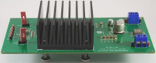
An extensive series of tests based on a 100 W buck converter determined the impact of the heat sink, its size, and its position on the MOSFETs junction temperature. The measurements also include a comparison between MOSFETs with an exposed pad on the bottom side versus MOSFETs with an exposed pad on the top side, a so-called “top cool” package.
Benefits of Top-Side Cooling Technology for PCB Design
Top-side cooling technology is an effective solution that offers several benefits for PCB design besides its critical impact on thermal management:
- Better Mechanical Stability
Top-side cooling technology offers better mechanical stability than traditional bottom-side cooling techniques. Attaching the heat sink directly to the top of the power semiconductor components significantly reduces the risk of mechanical stress or damage, which results in improved reliability and a longer lifespan of the components.
- Improved EMI Performance
Top-side cooling technology offers improved EMI performance compared to traditional bottom-side cooling techniques. By reducing the amount of electrical noise generated by the power semiconductor components, top-side cooling technology helps to ensure compliance with EMI and EMC standards.
- More Compact Design
Top-side cooling technology allows for a more compact design than air cooling, which requires additional space for fans or other cooling devices. By eliminating the need for additional cooling components, top-side cooling technology reduces the overall size and weight of the system, which is critical for automotive applications where space is often limited.
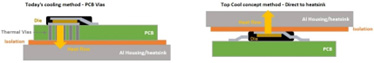
In real-world applications, where the PCB area is limited with less copper area, most of the heat generated would escape from the housing of the ECU. Top cool packages are the right fit for such conditions, with an exposed pad on top making direct contact with the housing. Most of the heat flows from the top side, and a moderate amount of heat flows from the bottom side through the PCB, which does not make the PCB warmer as otherwise seen on the traditional bottom-side exposed pad package. Enabling heat flow from both sides improves the PCB lifetime and extends system reliability.
The 100 W buck converter board is optimized with a larger area of copper in all layers, without significant difference in thermal performance between top and bottom-side exposed pad packages. But it is a good indication to show the importance of the PCB layout and obtain remarkable thermal performance without any expensive cooling systems.
The measurement results are shown in clearly arranged graphical comparisons and can be surprising. Of course, this test setup is far from an actual application, such as a power supply as part of a complex ECU inside a custom aluminum housing with cooling fins. However, it explains the impact of the different parameters, like the heat sink’s thermal resistance or gap pad thickness, on the MOSFET temperature. Also, It shows clearly that either mounting the heat sink on top of the heat source (the MOSFETs in this case) or the other side of the PCB can achieve similar performance. This presumes the PCB layout is thermally optimized with thermal vias and larger copper areas on all layers to allow thermal flow through the PCB. MOSFETs with a top-side exposed pad should connect to a heat sink to minimize heat flows into the PCB.
Please refer to our new white paper: Cooling Concept Assessment for High Power Step Down Conversion. It conveys the underlying significance of using a heat sink to reduce thermal stress on electronic devices and the dependency of system thermal performance on various factors, such as the position and size of the heat sink.
Improved Thermal Management Performance
Effective thermal management is critical for high-power step-down conversions in automotive applications. Traditional bottom-side cooling techniques have limitations, and new solutions are required as power densities continue to increase.
Top-side cooling provides a more direct thermal path for heat dissipation, which allows for better heat transfer from the power semiconductor components to the heat sink. This results in lower operating temperatures and improved efficiency, critical for high-power step-down conversions in automotive applications. Top-side cooling technology can provide up to 70% improvement in thermal performance compared to traditional bottom-side cooling techniques. This is due to the more direct thermal path provided by top-side cooling, which allows for better heat transfer and dissipation.
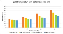
The paper clearly explains the test setup, loss calculations in the MOSFETs to set the expectations from the measurements, and measurement data from 10 mm, 25 mm, and 60 mm height heat sinks. It is fascinating to see how the fin height of the heat sink has an impact on thermal resistance. In real-world applications, even the heat sink height is considered carefully per the space availability and cost. Additionally, testing gap pads with different thermal resistance show the impact of heat transfer from the heat source to the heat sink. Around 30°C temperature difference is seen on MOSFETs without heat sink compared to those with heat sink; different heat sinks and load currents reveal similar noticeable differences. Measurement results align well with the theoretical expectations. Factors like cost, space availability, and plenty of others play a role in selecting the right cooling system.