level. To reduce the probability of component failure.)
Introduction
Solid tantalum capacitors are characterized with a “Fb” basic failure rate (FR) level. To reduce the probability of component failure, the devices should be chosen with respect to application conditions. For this purpose, users have to follow some basic recommendations – namely temperature derating, voltage derating, and current limitation.


FR = Fv x Ft x Fr x Fb, where:
Fv – correction factor due to DC voltage derating
Ft – correction factor due to operating temperature
Fr – correction factor due to added series resistance
Fb – basic failure rate level (1 % / 1000 unit*hours for standard products)
While temperature derating is not always possible in some applications (for instance, automotive), the application’s DC voltage should always match the capacitor’s voltage rating. This is especially important for capacitors with rated voltages of 35 V and higher.
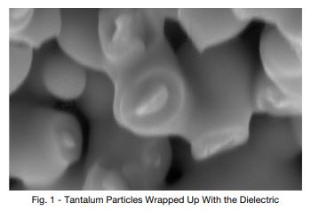
Basics of tantalum capacitors
The ability of a solid tantalum capacitor to withstand applied DC voltage is determined by the thickness and integrity of its dielectric layer.
To create the dielectric layer, the tantalum pellet’s (slug) surface is oxidized (anodized) to form tantalum pentoxide (Ta2O5). This is done by placing the pellet in an electrolyte bath (usually a diluted acid) and applying the DC formation voltage (FV).
For each volt of the FV, a layer of tantalum pentoxide ~17 angstroms thick is formed (an angstrom equals 10-8 cm, or 0.1 nm). For each specific rating (rating is a combination of capacitance and voltage), the minimum dielectric thickness is defined by the FV, which is about three times higher than the rated voltage (RV). The thicker the dielectric layer, the better its ability to withstand applied electrical stress in working environments.
Solid Tantalum Capacitors
(With MnO2 Electrolyte) Voltage Derating
Dielectric and crystallization
An ideal dielectric layer for a tantalum capacitor has an amorphous structure with very high resistivity to direct electrical current. Ratings with higher RV require higher FV for building the thicker dielectric layer. Higher FV forms a thicker dielectric, but the higher energy involved during this process makes it more prone to forming local Ta2O5 crystalline inclusions.
Therefore, the probability of such defects in dielectric layers thicker than about 100 nm increases, making them more sensitive to thermo-mechanical stresses (for example, in the reflow process). Once the Ta2O5 dielectric crystallizes, its conductivity and the leakage current (DCL) of the capacitor increases.
To minimize this sensitivity, Vishay applies healing steps at various stages of the solid capacitor manufacturing process. However, Vishay recommends added caution and a conservative approach to derating for capacitors with rated voltages of 35 V or higher.
Derating recommendations
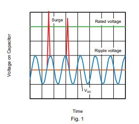
In working conditions, the voltage on the capacitor is the sum of the DC bias and AC ripple voltage, plus any possible transient peaks. The sum of these voltages (working voltage) should not exceed the RV. This means that the DC voltage applied to the capacitor has to be lower than the RV in order to leave room for the AC ripple voltage and any possible transients, spikes, etc. (see Fig. 2).
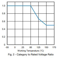
The maximum working voltage is equal to the RV in the temperature range of -55 °C to +85 °C; then it decreases linearly to 2/3 x RV at the maximum working temperature of +125 °C (for the 293D / TR3 / TP3 series and similar; for series with higher maximum operating temperatures, like the TH3 / TH4, it will go down to 0.5 x RV at extreme temperatures). Above +85 °C, it is common to refer to it as the category voltage. For the ratio between the RV and category voltage, refer to Fig. 3 below.
Commercial-grade solid tantalum capacitors with MnO2 electrolyte, when used at +85 °C with applied voltage equal to the RV and with a 1 series resistor (per each applied volt), are characterized with a FR of 1 % per 1000 working hours. If the applied voltage is less than the RV, and / or the temperature is less than +85 °C, and / or the resistor is > 1 (per applied volt) – then the FR decreases very significantly.
Vishay – along with other manufacturers of tantalum capacitors – recommends derating the DC voltage in order to decrease probability of dielectric breakdown at switch on / off and / or to increase the long term reliability of the capacitors. Similar recommendations are provided by the EIA-809 “Solid Tantalum Capacitor Application Guide” and relevant NASA and military specifications. Usually the recommendation is that the application (working) voltage be between 0.6 to 0.5 of the RV. For rated voltages 35 V, Vishay recommends an even higher derating ratio. The following table shows a practical approach to derating for several popular voltage rails (working voltages).
| RECOMMENDED VOLTAGE DERATING GUIDELINES (below 85 °C) | |
| VOLTAGE RAIL | CAPACITOR VOLTAGE RATING (V) |
| ≤3.3 | 6.3 |
| 5 | 10 |
| 8 | 16 |
| 10 | 20 |
| 12 | 25 |
| 15 | 35 |
| 24 | 50 or series configuration |
| 28 | 63 or series configuration |
| ≥32 | 75 or series configuration |