


Description
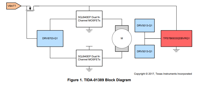
The TIDA-01389 is a small-footprint motor control module intended for sunroof and window lift applications. This TI Design uses the DRV8703-Q1 gate driver with an integrated current-shunt amplifier alongside two dual-package automotive-qualified MOSFETs, to create a very small power stage layout compared to typical relay solutions. This design also includes two of TI’s DRV5013-Q1 latching hall sensors, which are used to encode the motor position.


 Features
- 15-A Motor Drive
- Low Component Count
- Anti-Pinch Detection
- Reverse Battery Protection
- 2-bit Hall Encoder
- Motion Profiling Using Pulse Width Modulation (PWM) Input
Applications
- Power Sunroof
- Power Window Lift
- Brushed DC Pumps
 1 System Overview
1.1 System Description
The TIDA-01389 is a small-footprint power sunroof module designed to show the board space savings and integrated feature set of several TI automotive-qualified devices. This design includes TI’s DRV8703Q1 gate driver, DRV5013-Q1 latching hall sensors, and TPS7B6933QDBVR-Q1 3.3-V low-dropout (LDO) regulator. The key characteristics and reasons for design selection are outlined in the following sections.
1.2 Key System Specifications
Table 1. Key System Specifications
| PARAMETER | SPECIFICATIONS |
| Input voltage | 5.5 to 45 V |
| Maximum motor current | 15 A |
| Encoder type | 2-bit Hall sensor rotary encoder |
| Logic voltage | 3.3 V |
| Reverse battery protection | -60 V |
| Device qualification | AEC-Q100 and AEC-Q101 |
| Anti-pinch | Integrated current shunt amplifier |
| Sleep current | 2.729 mA |
| Operating current (no motor) | 10.215 mA |
1.3 Block Diagram
 1.4 Highlighted Products
1.4.1 DRV8703-Q1
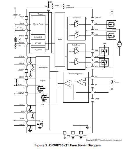
The DRV8703-Q1 is an H-bridge gate driver IC that controls four external MOSFETs arranged in an H-bridge configuration in this design. This device offers a high level of integration, which is used in this design for anti-pinch detection, overcurrent protection (OCP), undervoltage protection (UVP), and overtemperature protection (OTP). The integration of these features into the motor driver provides a high level of safety without the added discrete logic or various sensors.
The DRV870x-Q1 family of devices is a single H-bridge gate driver that uses four external N-channel MOSFETs targeted to drive a bidirectional, brushed DC motor. A phase / enable (PH/EN), independent H-bridge or PWM interface allows simple interfacing to controller circuits. An internal-sense amplifier provides adjustable current control. The gate driver includes circuitry to regulate the winding current using fixed off-time PWM current chopping. The DRV870x-Q1 family of devices drives both high-side and low-side FETs with a 10.5-V VGS gate drive. The gate-drive current for all external FETs is configurable with a single external resistor or through the serial peripheral interface (SPI). A low-power sleep mode is provided, which shuts down internal circuitry to achieve a very-low quiescent-current draw.
Figure 2 shows the functional diagram of the DRV8703-Q1.
 1.4.2 DRV5013-Q1
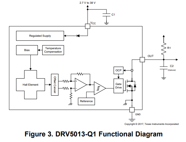
The DRV5013-Q1 device is a chopper-stabilized Hall effect sensor that offers a magnetic-sensing solution with superior sensitivity-stability overtemperature and integrated protection features. Two of these devices are used in this design to encode the speed and direction of the motor used for opening and closing a sunroof.
The magnetic field is indicated through a digital bipolar latch output. The IC has an open-drain output stage with 30-mA current sink capability. A wide operating voltage range from 2.7 to 38 V with reverse polarity protection up to –22 V makes the device suitable for a wide range of automotive applications. Internal protection functions are provided for reverse supply conditions, load dump, and output short circuit or over current.
Figure 3 shows the functional diagram of the DRV5013-Q1.
 1.4.3 TPS7B6933QDBVR-Q1
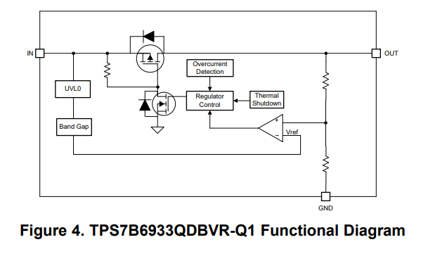
The TPS7B69xx-Q1 device is an LDO linear regulator designed for up to 40-V operation. With only 15-µA (typical) quiescent current at light load, the device is suitable for standby microcontrol-unit systems, especially in automotive applications. The devices feature an integrated short-circuit and load current overcurrent protection. The TPS7B69xx-Q1 operates over a –40°C to 125°C temperature range. Because of these features, the TPS7B6925-Q1, TPS7B6933-Q1, and TPS7B6950-Q1 devices are well-suited in power supplies for various automotive options applications.
The TPS7B6933QDBVR-Q1 is used to create a 3.3-V rail that powers the Hall sensors and other logic devices in this design.
Figure 4 shows the functional diagram of the TPSB6933QDBVR-Q1.
 2 System Design Theory
2.1 Gate Drive and Power Stage
The first component of this design is the DRV8703-Q1 gate driver. This device is used to control the four MOSFETs connected in an H-bridge configuration for bidirectional motor control. Using a gate driver for this application allows for a high-level integration and supervisor protection of the external MOSFETs. The DRV8703-Q1 has an integrated current-shunt amplifier, which is connected to the sense resistor R1 as shown in Figure 5. In this design, the output of the current-shunt amplifier is connected to the LaunchPad headers to allow for external monitoring of the current flowing through the motor.
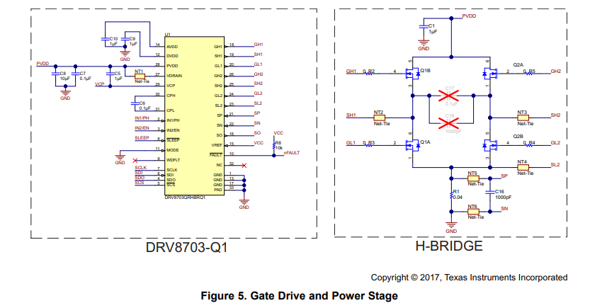
While the DRV8703-Q1 offers the output of the shunt amplifier, the device also has an internal current supervisor that can be adjusted to set an automatic current limiting level. When the device detects that the current in the system is above this level, the device will turn off the external MOSFETs until the beginning of the next PWM frame.
2.2 Reverse Battery Protection and Electromagnetic Compatibility (EMC) Filter
To protect the circuits connected to the positive battery terminal from reverse voltage, this design includes a high-side MOSFET switch, which is shown in Figure 6. This circuit will stop Q5 from conducting when the battery terminals are reversed, which prevents any devices on the PCB from being damaged.
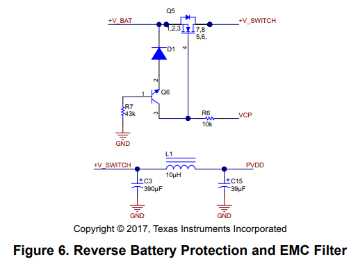 This circuit also includes a process integration (PI) filter designed to limit the conducted emissions that could interfere with other devices sharing the battery rail. This filter was designed to meet the current specification of up to 15-A maximum current through the inductor and up to 40 V across the capacitors.
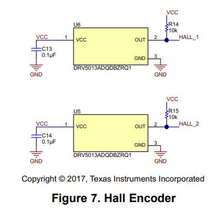
2.3 Hall Sensor Encoder
In order to determine the number of rotations the motor has turned, two DRV5013-Q1 Hall sensors are used to encode a barrel magnet attached to the motor. Both hall sensor ICs can be laid out as shown in Figure 7.
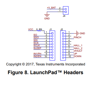
 2.4 LaunchPad Connections
To allow for simple evaluation of the motor driver and power stage, the LaunchPad headers J1 and J2 are included for connections be made quickly using different types of microcontroller (MCU) platforms. All of the connections needed for the DRV8703-Q1 SPI and motor control are included on these connections, as well as ground, 3.3 V, and both Hall sensors. The pinout of these two LaunchPad connections is shown in Figure 8.
3 Relay Comparison
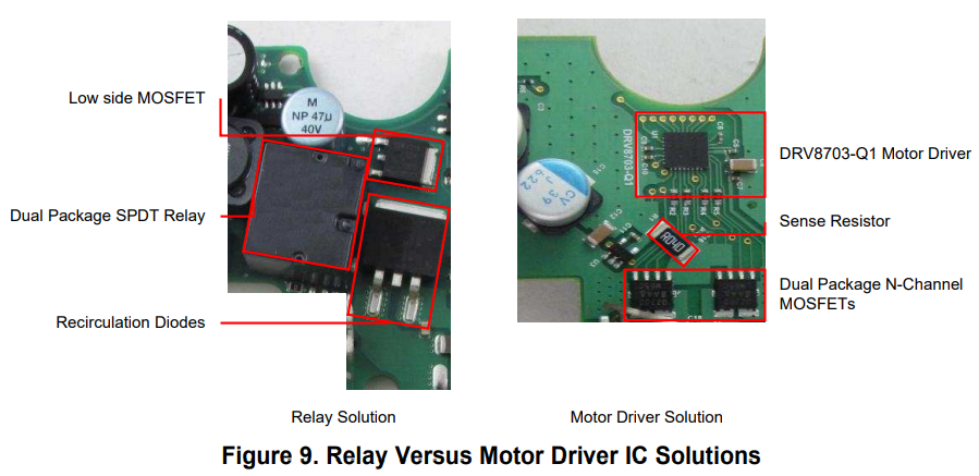
In the past, many automotive motor applications used relays to control the direction of current through the motor. This reference design illustrates the size and component-count savings that can be found by using a gate driver and MOSFET solution instead of the traditional relay solution, as shown in Figure 9.
Table 2. Relay Versus Motor Driver IC Comparison
| DUAL SPDT RELAY | DRV8703-Q1 GATE DRIVER |
| Limited mechanical switching lifetime | Unlimited switching lifetime |
| External diodes required for current recirculation | Brake or coast motor with no extra components |
| Discrete components required for digital interface | Simple digital interface for MCU control |
| External shunt amplifier required for anti-pinch current monitoring | Integrated shunt amplifier for current monitoring |
| Protection implemented with external circuits | Integrated temperature and over current protection |
Table 2 lists the layout comparisons of the DRV8703-Q1 and a typical relay solution. By integrating protection features as well as a current-shunt amplifier, the DRV8703-Q1 saves a large amount of board space in comparison to relay solution requiring different external circuits for protection and current monitoring. The MOSFETs selected for this design are dual-package, N-channel MOSFET devices rated for 40-V, 15-A continuous automotive applications. The relay shown in Figure 9 above has a similar specification, however, is significantly larger in size. By using these small footprint MOSFETs and the DRV8703-Q1 in this designs power stage, the total solution size is approximately the same area as the relay in Figure 9.
4 Getting Started Hardware
4.1 12-V Supply
This design is intended to run on a 5-V rail and will require 1.3 A when all LEDs are active. A capable power supply should be connected to J2.
4.2 Motor Module
To test this reference design, a typical motor and worm wheel gear were used to test the encoder and motor driver solution. The different components required to test this design are outlined in Figure 10.
The barrel magnet (as seen in Figure 10) is constructed so that the different pole segments are out of phase with the two Hall sensors placed on the PCB in Figure 11. The outputs of the two Hall sensors are approximately 90° out of phase with each other, which creates a simple quadrature encoder. This encoding type is outlined in Section 5.1.
This motor module also includes a worm wheel assembly. The brushed DC (BDC) motor is attached to a worm screw, which translates the high-speed, low-torque of the BDC to a low-speed, high-torque on the worm wheel gear. This worm wheel gear can then be attached to a window assembly to provide a significant amount of lifting torque without requiring a large motor or large currents flowing in the controller circuit.
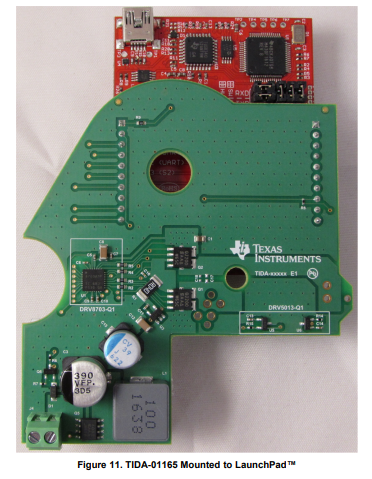
4.3 LaunchPad Mounting
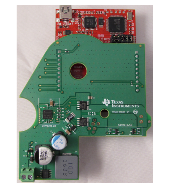
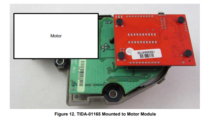
In order to evaluate the motor drive stage in this design, the board can be mounted to any variation of TI LaunchPad to test with different MCUs. In Figure 11, TIDA-01165 is mounted to an MSP430G2553 LaunchPad. Any MCU variant or LaunchPad could be used, but the G2553 was selected for simplicity in this brief evaluation.
To mount the reference design with a LaunchPad, simply connect the headers J1 and J2 on the TIDA01165 PCB to the control pin headers of the LaunchPad variant selected. Be sure to note polarity of the 3.3-V and GND connections.
 Once a LaunchPad is mounted to the reference design, the two PCBs can be connected to the motor module. TIDA-01165 is mounted to the terminal clips and can then be evaluated, as shown in Figure 12.
 5 Testing and Results
5.1 DRV5013-Q1 Hall Encoder
Two Hall sensors are used in this design to encode the rotation of the BDC motor shaft. Both Hall sensors are spaced on the PCB so that the encoder bits are separated by approximately 90°. If the direction of motor rotation is changed, the pattern of Hall edges will be reversed. This pattern can be measured detecting the Hall transitions as shown in Figure 13 and Figure 14.
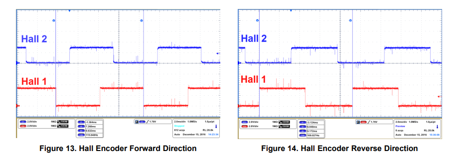
In this design, the two Hall sensor outputs are tied to pins 6 and 7 of the LaunchPad header J2. These two pins can be monitored to determine:
- Number of rotations
- Speed of rotation
- Direction of rotation
- Stall detection
5.2 Motion Profiling
By using the DRV8703-Q1 and the external N-channel MOSFETs, different motor speed profiles can be achieved for starting and stop motions. The DRV8703-Q1 can be configured to use a PH/EN interface where the device will take one PWM signal and a single GPIO bit to control the direction of rotation.
By using this simple interface, the MCU used to supply the drive signals to the DRV8703-Q1 only needs to supply a single PWM signal and one GPIO bit, which means the MCU used for motor control can be relatively simple.
By using the single PWM signal, the motor speed can be tightly controlled to ramp the speed of the motor up or down as it begins or ends its range of travel. For applications like sunroof modules, the speed of the glass can be adjusted to provide a smooth start and stop.
5.3 Shunt Amplifier Anti-Pinch Implementation
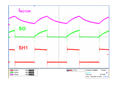
In this design, the DRV8703-Q1 monitors the voltage across the sense resistor R1. The current at which the DRV8703-Q1 begins limiting current in the motor can be calculated using Equation 1.
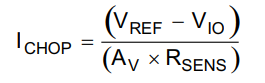
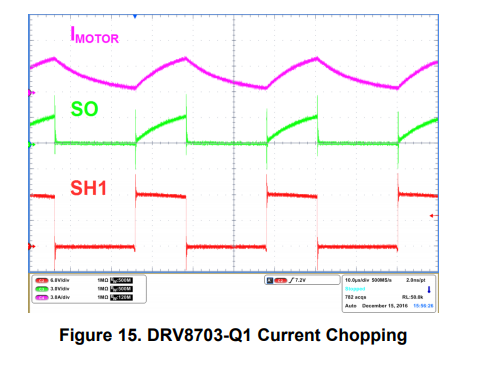
Once the ICHOP threshold is exceeded, the DRV8703-Q1 disables the MOSFETs in the external H-bridge for the remainder of the PWM frame. At the start of the next PWM frame, the DRV8703-Q1 begins driving current through the motor terminals until the ICHOP threshold is again exceeded.
While the DRV8703-Q1 will limit current at this limit, the output of the integrated-shunt amplifier can still be monitored to determine how much current is flowing through the system. An example of the DRV8703-Q1 operating in current chopping mode is shown in Figure 15.
Article Courtesy: Texas Instruments