


There are many confusing specifications that are centered around a converter’s bandwidth. What bandwidth term(s) should I use in order to choose an appropriate converter for my next design?
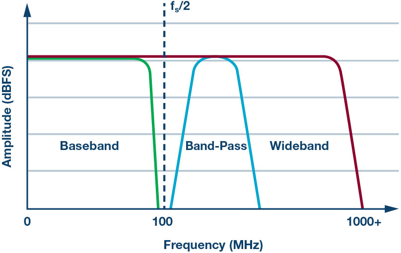
When starting a new design, the parameter that needs to be decided on first and foremost is bandwidth. Bandwidth will provide direction in the design and will allow the designer to start carving the path to success. Essentially there are three types of front ends to choose from baseband, band-pass or super-Nyquist (also sometimes referred to as narrow-band and/or sub sampling—basically you are not using the 1st Nyquist zone), and wideband, as shown in Figure 1. The application determines which front end should be applied.


Baseband designs require a bandwidth from dc (or the low kHz or MHz region) to the Nyquist of the converter. In terms of relative bandwidth, this implies about 100 MHz or less, assuming a sample rate of 200 MSPS. Designs like these can employ an amplifier or transformer/balun.
A band-pass design means a small piece of the converter’s bandwidth (that is, <Nyquist) is going to be used at high IFs. For example, the requirement might only be 20 MHz to 60 MHz and centered at 170 MHz—again, assuming 200 MSPS. However, trends show the market is targeting for even higher IFs, with the release of newer GSPS converter type offerings. So the example in the previous statement might be padded with an extra 0. In essence, the designer only needs a small piece of converter bandwidth to do the job. Typically, a transformer or balun is used here. However, an amplifier can be used if the dynamic performance is adequate at these higher frequencies and gain is required.
A wideband design usually refers to those designs that need it all. As much bandwidth as the converter will supply, the user will take—like drinking from a firehose! These can be the most challenging front-end designs since they have the widest bandwidth of the three. Even more challenging is if the design calls for 0.1 dB flatness across the passband. These applications require dc or low kHz/MHz regions to the +GHz region. These types of designs often employ a wideband balun to couple to the converter.
Notes on Bandwidth
The term bandwidth is tossed around loosely in engineering and, depending on the application, it can mean something completely different from one designer’s perspective to another’s. In this article, the converter’s full power bandwidth is different from a converter’s usable or sample bandwidth. Full power bandwidth is the bandwidth that the converter needs to acquire signals accurately and for the internal front end to settle properly. In most cases, the converter’s sample bandwidth target is dialed in at roughly two Nyquist zones. The converter is often characterized this way over its ac frequency specifications as well.
A designer selecting an IF outside the converter’s specified region is not a good idea, as ac performance results will widely vary in the system, despite the rated resolution and performance stated in a converter’s data sheet, or shown full-power bandwidth, being much bigger (possibly 2×) than the sample bandwidth of the converter itself. Sample bandwidth is what the design is centered around. All designs should avoid using some or all of the highest frequency portions of the rated full power bandwidth— by doing so, expect a derating in dynamic performance (SNR/SFDR). To determine the sample bandwidth of a high speed analog-to-digital converter, consult the data sheet or application support, as sometimes the sample bandwidth isn’t specially given. Typically, the data sheet has specified or even listed production tested frequencies that guarantee delivered performance within the converter’s sample bandwidth. However, better explanations about these bandwidth terms in the industry need to be specified and defined.
Understanding Converter Bandwidth and Accuracy
All ADCs have a settling-time inaccuracy. Keep in mind that a converter’s internal front end must have enough bandwidth (BW) to accurately sample the signal. Otherwise, the accumulation of errors will be greater than what was described above.
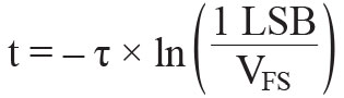
In general, an ADC’s internal front-end must settle within half a period of the sample clock cycle (0.5/fs, where fs = sample frequency) to provide an in-bounds accurate representation of the analog signal to be acquired. Therefore, for a 12-bit ADC sampling at 2.5 GSPS and a full-scale input range (VFS) of 1.3 V p-p, the full-power bandwidth (FPBW) required can be derived by starting with the transient equation:
![]()
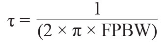
Solving for t:
Substituting in τ = 1/(2 × π × FPBW) for one time constant, and solving for FPBW:
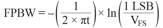
let t = 0.5/fs. That is the time needed for a sample to settle, where the sampling period is 1/fs:
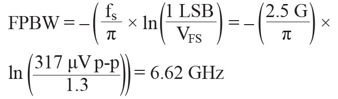
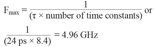
This will yield the minimum required bandwidth for the ADC’s internal front-end FPBW. The converter’s internal front-end needs this amount of bandwidth to settle within 1 LSB and sample the analog signal appropriately. It will require the passage of several time constants to meet an accuracy of 1 LSB for this type of ADC, where one time constant is equal to 24 ps, or:
To understand the number of time constants required for the full-scale range of the ADC in LSB size, %Full-scale error, or VFSE, needs to be found. Or, 1 LSB = VFS/(2N ), where N = number of bits; or
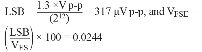
Table 1. Converter Resolution Breakdown
| Converter Resolution | Number of Bits | LSB Size | VFSE |
| 6 | 64 | 0.01875 | 1.5625 |
| 8 | 256 | 0.0046875 | 0.390625 |
| 10 | 1024 | 0.001171875 | 0.09765625 |
| 12 | 4096 | 0.000292969 | 0.024414063 |
| 14 | 16384 | 0.0000732422 | 0.006103516 |
| 16 | 65536 | 0.0000183105 | 0.001525879 |
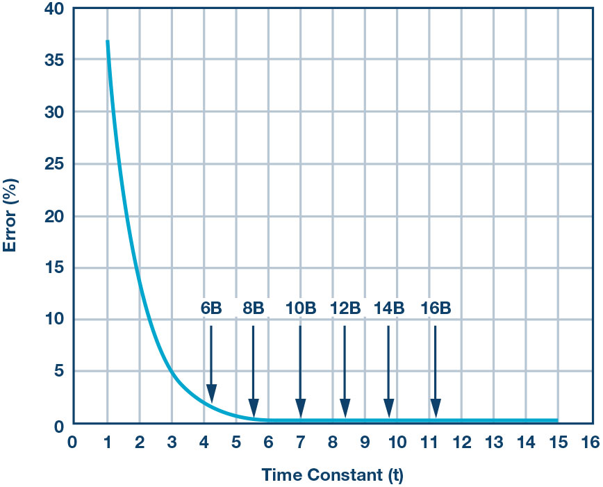
By plotting Euler’s number, or eτ, a graph can be developed that makes it easy to show the relative error with the passing of each time constant. In Figure 2, it can be found that it takes 8.4 time constants for the 12-bit ADC example to settle appropriately within 1 LSB.
This analysis allows designers to estimate the maximum analog input frequency, or sample bandwidth, that the converter can handle and still settle within 1 LSB of error. Beyond that, the ADC cannot accurately represent the signal. Thus:
 Keep in mind that this represents a best-case scenario, and the assumption is for a single-pole model ADC front end. Not all practical converters behave this way, but this is good starting point.
For example, the model described is valid up to 12 bits. However, for 14 or 16 bits and beyond, a second-order model should be used, because of subtle effects that can make settling time stretch out beyond the predicted first-order models.
Quiz:
Question 1:
What is the different between full power bandwidth and sample bandwidth?
Question 2:
Is a certain amount of time important for a converter to accurately represent a signal that it is acquiring within its bandwidth?
Question 3:
What is the difference between a baseband and a wideband design? You can find the answers at the StudentZone blog.
Rob Reeder, is a senior system application engineer with Analog Devices in the High Speed Converter and RF Applications Group in Greensboro, North Carolina.