Electronic multi-board systems design has traditionally been implemented as a set of separate, uncoupled board projects held together by some non-EDA technology definition of their intra-relationship and architecture. Teams usually use desktop office tools such as spreadsheets for intra-board connectivity, text files for system element parameters and drawing applications to show block-level system structure and hierarchy. The challenge with this disconnected approach is that the data must often be re-entered several times because no standard synchronization methods between different disciplines and domains were available.
Disconnected creation of cable/back- plane interconnect schematics, in conjunction with a weak connector management process explains why many companies build expensive prototypes to overcome their inherent design methodology weaknesses. The high investment of time and resource results in a significant effort to manually correct connectivity errors or to manually synchronize boards and cables. Often, enforcement of restrictive change rules or naming conventions is required to minimize the risks of errors.


Most system failures are related to wrong connectivity including connector pin swaps, wrong connector orientation, mechanical incompatibility or incorrectly mated connectors. These are issues that would not happen if teams used a connectivity-based multi-board systems design solution.
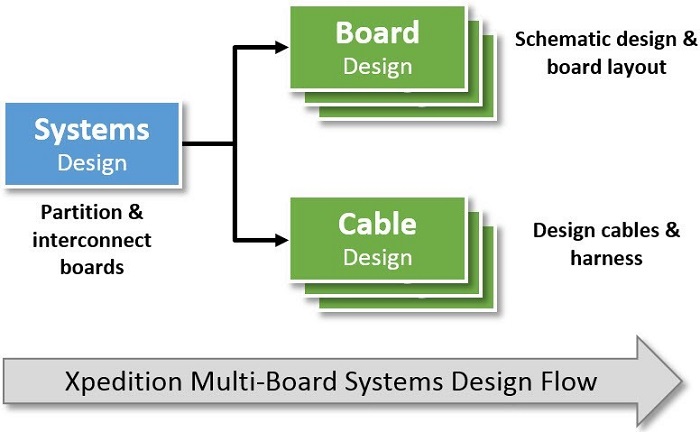
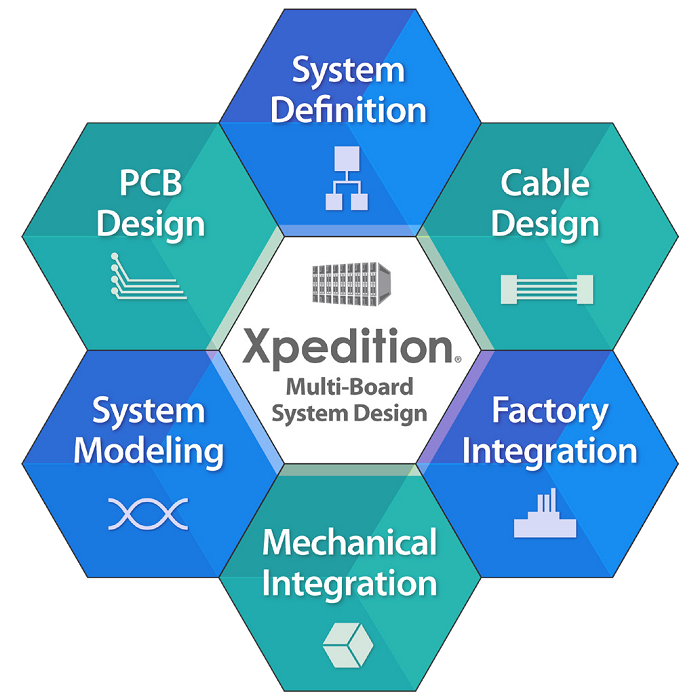
Mentor Graphics Xpedition multi-board systems design solution addresses these challenges using automated connectivity and a correct-by-construction solution that extends the PCB design flow into the electronic multi-board system definition. It applies innovative and best practice data and connectivity management capabilities to the entire system definition and implementation flow. This significantly reduces manual tasks and allows more time to optimize the system implementation to the required specification, while increasing overall quality and reducing schedule risks. Xpediton’s system design environment integrates with the PCB design flow and the unique work-in-progress design data management hub, extending it to full systems design, including multi-board system definition, partitioning, optimization and implementation. This allows designers to catch errors before any hardware is constructed. Xpedition provides a unique environment for PCB and cable and harness designers and other engineers to concurrently develop complex multi-board systems.
Systems Design Automation
Xpedition allows the project architect to define and capture the hardware description at the logical system level down to the logical/PCB level, including the logical definition of wires, cables and backplanes.
Primarily targeted to capture the full system connectivity, the cockpit extends to other areas, such as design validation and requirement tracing.
Integration with the data management backbone provides a comprehensive infrastructure to securely manage the complex development process of many individual project components through revision management, access control and release and information management of work-in-progress system design data, including single board and cable designs.
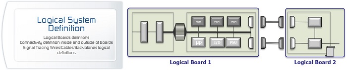
System Definition
System definition capabilities allow a system designer to visualize and implement the system engineer’s design intent, to create optimal function location and interconnectivity across the system. The key element in the system definition is a logical board. Designer defines logical boards at the logical system view level by simply grouping system-level blocks and on-board connectors. This process is straightforward and very intuitive. The designer simply partitions system functions using system-level blocks that will play the role of regular hierarchical blocks later in the PCB design. The designer can create the system level block locally, place it from the corporate library, or reuse existing PCB design portions.
Connector Management
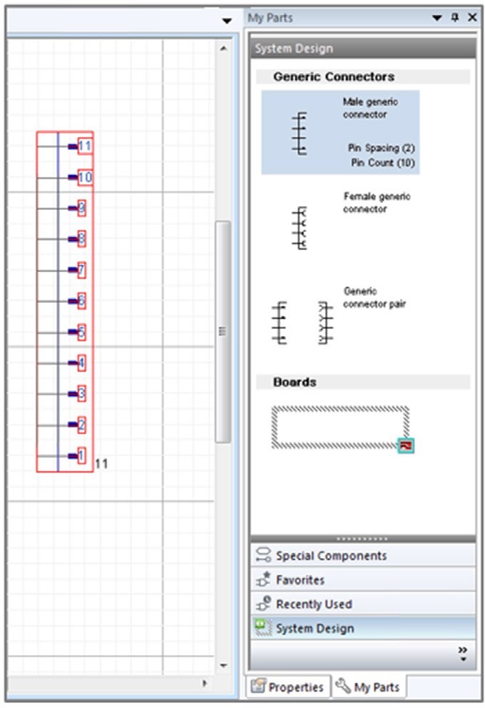
The tool minimizes the effort to add, manipulate and update connectors with on-the-fly creation of parameterized connectors (compliant with IEC standards) with connector expansion and pin number modification by using a simple stretch command. The high degree of automation enables designers to create and modify connectivity using generic connectors without concerning themselves with the actual physical details of the connector.
Connector management enforces a “correct by design” approach, eliminating connection errors upfront and any- time during the overall system design cycle and it provides automated mating and pin pairing of connectors.
Connectors are intelligently managed by:
- Synchronization between the physical PCB, cable implementation and the system design data
- Automated choice and assignment of possible mated connectors
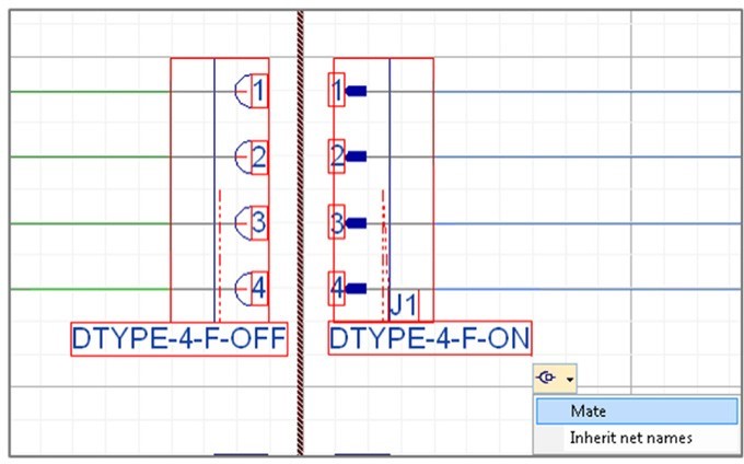
needed and when possible.
Board Intelligence – System Optimization
After connectivity changes between the board, as defined at the system level and the corresponding, associated PCB project, the designer can bi-directionally synchronize both definitions which allows implementation flexibility.
For example, due to new mechanical constraints, a board definition needs to be modified at the logical system view level. This is easily accomplished by dragging the system level blocks between logical boards. As objects are moved between logical boards, connectivity is automatically updated.
Connectors are automatically inserted and required connections are created on the fly and transformed between nets and wires. However if the designers change their mind, it is possible to move the block back to the original position at any time and the connectivity is automatically updated.
Requirement changes are quickly and seamlessly absorbed without jeopardizing the whole system design.
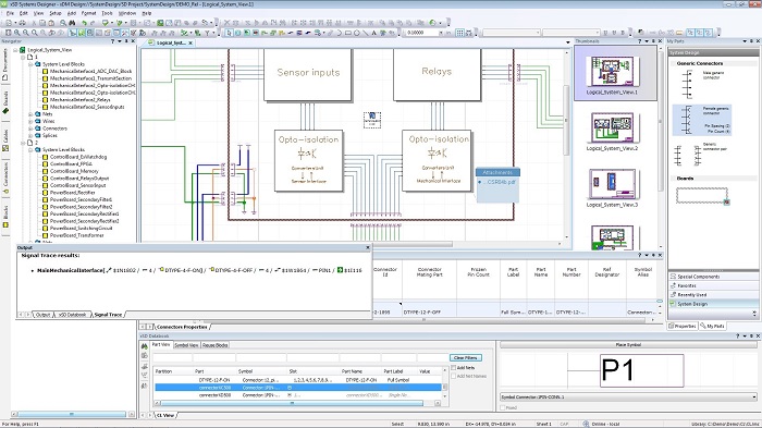
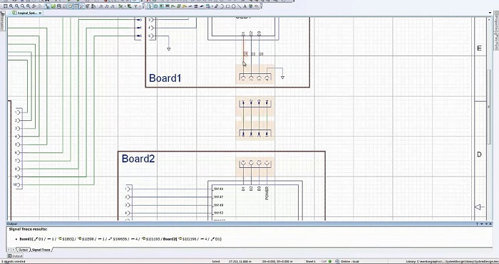
Highly Automated Interconnectivity and Connectivity Verification Xpedition automates the process of creating connections between system elements, including connection order and wiring of multiple nets and wires. To increase productivity the tool provides the capability to connect multiple pins at once.
The designer can easily cross-probe from the signal trace output to find and select the specific object belonging to the signal path. For example, the designer can find the net connected to the specific connector pin. Connectivity verification capabilities ensure that connectivity is exactly as the designer wants it to be. The signal trace functionality is able to trace signals through the pair of mated connectors and paired pins, and even objects that are located on different sheets. Color coding and highlighting enable the designer to easily trace connectivity across the entire system.
Multi PCB and Cable Integration
After the designer creates associations between logical boards and PCB designs at the system level, the system designer can start to synchronize the content of logical boards and associated PCB schematics using a bi-directional process. A synchronization assistant provides the list of changes, a preview of the logical board definition and colour coding that clarifies the synchronization status of particular objects. This window provides a multitude of tips to help solve problems and to provide useful information for new users. Because the PCB schematic is synchronized with associated logical boards, the PCB schematic contains connectors and system-level blocks that are, in effect, hierarchical blocks.
Therefore, board designers can push into these blocks and define logic on the underlying schematic to realize each specific function of the system.
The synchronization process is not automatic but is controlled and well managed so that the synchronization tasks are executed only by responsible designers. The software tracks changes between boards and their content, connectivity between the boards and pin-to-pin relationships between connectors.
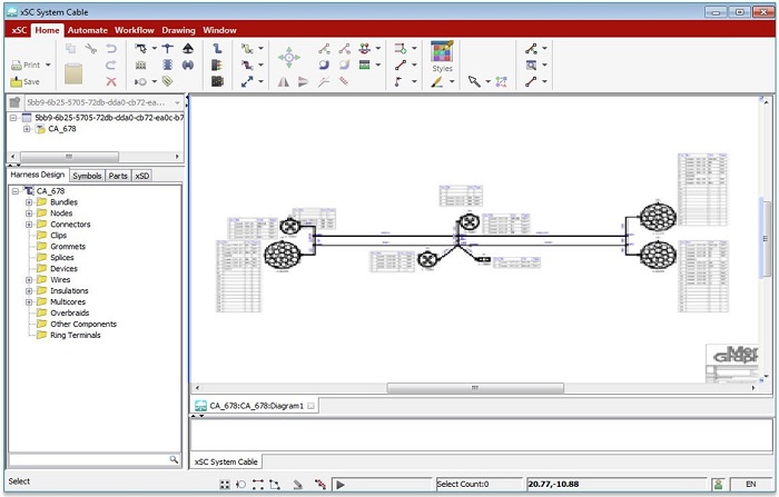
Integrated Cable Design
In some multi-board systems, the interconnection between boards and other system components (such as sensors) is implemented by cabling. Logical system connectivity can be simply partitioned into multiple cables. Each logical cable requires physical representation. The tool has a variety of features to auto- mate selection of parts by automatically adding wires, multicores, terminals, tapes, and all other cable components for ready-to-manufacture cable designs including bill-of-materials and manufacturing drawings. Automatic calculation of quantities (e.g. ‘true’ manufacturing wire lengths) ensures correct-by-construction cables. Tight integration between ECAD and MCAD environments is essential for an efficient system design process. Mechanical designers can collaborate with cable designers by exchanging critical design decisions that impact each other’s design.
System Design Reuse
Most of the time, designers have associated documentation that needs to be kept together with specific system design elements. The Xpedition multi-board system design solution allows designers to specify additional information and to add more details to system objects, such as system-level blocks. The benefit of this feature is to keep the data intact and where designers can easily access it, even in a dynamically changing environment.
Designers can also leverage existing IP by importing and embedding Microsoft Visio data into the system design. This capability extends beyond simple object linking and embedding by converting the Visio objects to regular Xpedition system design objects. Designers can then perform full editing and modification of the individual objects.
Collaborative Concurrent Design
Xpedition and its work-in-progress design management hub moves engineering collaboration to a new level. Multi-board systems design is a business process that engages numerous disciplines. Xpedition provides the integration between these disciplines by only passing key data between them. The tool understands how elements in one discipline are dependent on elements in another discipline and it pro-vides notifications when a dependent element changes. The tool liberates design data from the desktop and provides controlled, unified data storage. The Xpedition multi-board systems design solution provides an all-domain collaboration client that operates on the versioned, unified data with notification, cross-probing, mark-up and comments. The solution provides consistent, integrated design process management. It supports:
- Flow-wide, unified design data synchronization processes
- Synchronization managed through the work-in-progress design management hub using a familiar bidirectional forward/back-annotation process between the system, PCB and cable levels and tools
- Exactly the same mechanism as the traditional synchronization process between schematic and board layout
Controlled data access to PLM and 3rd parties via the standard EDX I/F
Summary
Xpedition sets the standard for fully integrated multi-board system design creation by:
- Eliminating manual and error prone multi-level design synchronization processes
- Providing electronic versus paper design team collaboration
Within this solution, Siemens offers unique features to match the designer’s expectations in the multi-board systems design creation space:
- Easy to deploy, easy to adopt and easy to use
- Enables concurrent (parallel) versus serial team design
- Efficient data management
- Scalable functionality