


Mark Smith, Microchip technology
Inductive position sensors measure linear and rotational angles precisely in harsh conditions, but sometimes a less accurate second axis of movement is needed. While a second position sensor can be added for precise measurements, Microchip’s inductive position sensor ICs allow for a second axis to be measured with just a single sensor.


How to Measure Two Dimensions
Inductive position sensors can accurately measure rotational or linear positions of a metal target. Unlike other magnetic field sensors, they don’t need a magnetic target. Instead, they use an alternative magnetic field to induce a magnetic field in a metal target and then are able to precisely measure the position of the target. This target can be any metal, but the best targets are copper, aluminum or stainless steel. Although they are great for measuring linear distance and rotational angles, sometimes more than one dimension is needed in an application. For precise measurements, a second inductive position sensor can be added to measure this additional axis, but this second axis does not always require the same level of accuracy—for example, a rotary knob with a push button function or an automotive gear shifter with a manual shifting feature by pulling the gear to the left or right. In either, a threshold value with some margin may be acceptable.
With our LX3302A inductive position sensor, you can add the measurement of a second axis. After describing how it is done, we will present the steps to implement it in your two axis sensor design.
How Our Inductive Position Sensors Measure a Second Dimension
Microchip’s unique use of a fast continuous automatic gain control (AGC) circuitry with inductive sensors helps to provide both accurate measurements and enables this second axis of measurement. The figure below illustrates the block diagram of the inductive position sensor and the operation of the AGC. The magnetic field is introduced in the metal target by the OSC1 and OSC2 signals. The receive signals, CL1 and CL2, are demodulated to represent Raw Sin(x) and Raw Cos(x), where x represents an angle or position. The amplitudes of these signals are read by a fixed input range analog-to-digital converter (ADC) to transform the signal into the digital domain. A microcontroller then can determine the precise angle or position, x, using the sin(x) and Cos(x) values to calculate arctan(x) along with other calibration algorithms.
![]()
To maximize the resolution of these ADC readings, the AGC is adjusted to ensure the peaks of the Sin(x) and Cos(x) will stay at the maximum range of the ADC over different signal strengths. It does this by controlling the OSC1 and OSC2 amplitudes
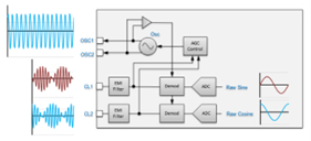
Figure 1. Analog Front End (AFE) Block Diagram of the Inductive Position Sensor
using the following trigonometry identity as a control law:
![]()
where x represents and rotational angle or measured distance. The AGC(x) is then calculated by the following equation:
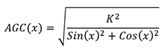
where AGC(x) is the gain at every angle or position x and K is a constant radius defined by the circuitry. The control law and block diagram illustrate that as the target distance is adjusted, the received signals CL1 and CL2 will not increase or decrease because the AGC(x) will automatically change to keep the peak of sin(x) and cos(x) signals constant for the ADCs to read. We are going to use this AGC(x) gain to provide a second axis of measurement with just one inductive position sensor integrated circuit (IC).
Sensor Target Distance Changes Gain
Without the AGC, the receive signal strength of CL1 and CL2 would change with an air gap. Conceptually, with a larger air gap between the sensor and the metal target, the magnetic field generated by OSC1 and OSC2 will not induce as much magnetic field in the metal target and CL1 and CL2 will receive less signals. However, by implementing this continuous AGC, we now have a direct measurement of the air gap or distance between the sensor and target. As long as the sensor mechanical design can be adjusted to utilize this air gap, this second axis (i.e. z-axis) be used. The next question would be: how do we measure this gain?
A 10-Bit ADC to the Rescue
Microchip’s LX3302A, LX3301A and LX34211 have a 10-bit ADC to provide dynamic calibration. It does dynamic calibration by measuring the amplitude of the oscillator voltage, which represents gain, and using this to compensate for a non-ideal sensor’s offset voltage over different AGC gains. Sensor offset is defined as an addition of unwanted constant voltage present in the Sin(x) or Cos (x) signals:
![]()
The LX3302A has a special single edge nibble transmission (SENT) mode to transmit this ADC 10-bit gain information along with the primary axis position information.
Using More SENT Channel Bandwidth
The LX3302A is a versatile IC with four different methods to interface with an external host microcontroller or computer. It can output analog, PWM, SENT or PSI5 values of the sensors output as shown in the block diagram blow. You can also see the 10-bit ADC connection to the AFE block that measures oscillator voltage.
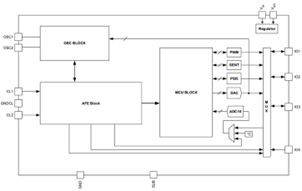
The single edge nibble transmission (SENT) of the LX3302A is one of the output interfaces and is a robust, noise immune communication method. The SENT protocol has two fast 12-bit channels and one slow 12-bit channel for transmitting information. The LX3302A SENT mode (FCM = 0100) utilizes the second fast channel to transmit this 10-bit ADC oscillator voltage while also transmitting the precise position information with the first fast channel. The 10-bit (0-1024) ADC value is transmitted over this second fast channel.
The host microcontroller can then use this information to determine the gain and air gap of the AGC and measure this second axis of motion. The application note on the LX3302A shows how to use a microcontroller to read this SENT information even when the microcontroller does not have a native SENT peripheral. In summary, in regards to our earlier example, a rotary knob with a push button indicator could use an air gap change to detect when the knob was pushed by the user.
Practical Considerations
Precise sensors will have very little sensor offsets (i.e. Offsin = Offcos = 0), but sometimes this is difficult to achieve. Using dynamic calibration, these sensors can also be accurate, but the oscillator voltage will end up moving over the measurement range. These sensors can also use this AGC gain to detect secondary axis movement, but may need to utilize the position sensor information. In an extreme example, the linear sensor below had an abnormally large offset, as can be seen by the oscillator voltage over the measurement range. Three different air gaps were measured.
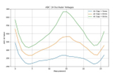
Figure 2. A sensor with a large offset voltage
Even under these conditions, using the position information, the air gap can be detected. If the goal is to detect when the air gap drops below 6.5 mm with some margin, then a 10-bit ADC value over position can be chosen that fits approximately at the 6 mm air gap curve. For example, at measurement position 5, if the ADC 10 bit value is less than 340, then the air gap is less than 6 mm. While at position 15, an ADC 10-bit value less 550 would detect the same 6 mm air gap.
Using the host microcontroller, the following air gap threshold curve can be used as an example for this extreme condition of implementing this secondary axis measurement with a sensor with a lot of offset.
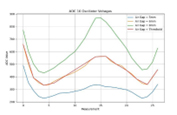
Figure 3. Using a variable threshold for the secondary axis threshold