


 intended to cover the range .)
Introduction
This blog post covers the construction of a voltage-controlled oscillator (VCO) intended to cover the range of approximately 98 MHz to 118 MHz (you can probably guess what use such an oscillator could have!), although this design could be modified for different ranges from tens of MHz to perhaps 500 MHz.


What it is?
The name of the project is fairly self-explanatory: ) It’s an oscillator where the frequency is determined by an input voltage signal. The input signal could be a steady voltage from (say) a variable potential divider, or it could be a faster-changing signal, either digital or analog, from a microcontroller or audio source for instance. Such a signal would modulate the output frequency (known as Frequency Modulation or FM).
Oscillator Design
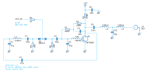
According to the book Oscillator Design and Computer Simulation, a bipolar junction transistor (BJT) can be a good choice for an oscillator in the VHF or UHF range. The book describes an example 300 MHz oscillator using a series inductor and capacitor (LC) circuit (L1 and C6 in the circuit diagram below, 100nH and 3pF respectively). I used that as a starting point, and increased the inductance to 210nH, and increased the capacitor to 9pF. The circuit had a couple of 33pF shunt capacitors C1 and C2, I doubled those to 68pF, but found that oscillations died off at around 115 MHz, so I reduced those and tried various values. I also experimented with the coupling capacitance between the base and the collector, and the feedback loop joining capacitance. The transistor I had chosen oscillated at unwanted frequencies so a ferrite bead was added at the base.
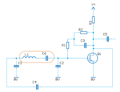
I went with the 210nH inductor for two reasons; firstly, because I wanted it to be easy to wind, and five turns of wire around a AAA sized cell with the turns spaced a reasonable distance apart (6mm total length) provided this inductance, and secondly, I could get the oscillations to be in the correct tuning ballpark by making a slight capacitance change in a range that would suit installing a varicap (also known as varactor) diode to replace C6 in the circuit diagram above. Such a diode exhibits a capacitance that changes as the reverse voltage across the diode is altered. The capacitance decreases with an increase of reverse voltage, but there is a practical range where the reverse voltage doesn’t need to be too high (which would mean having to run the circuit off a higher voltage than I wished).
I decided to use a dual varicap diode, BB914 and used an online series capacitance calculator to play with the capacitor values that would need to be installed in the circuit in series with the diodes, to achieve the desired range. I needed to use resistors to apply a reverse bias voltage on the varicap diodes that would allow the capacitance to change enough to cover the desired frequency range.
I also tried a higher inductance of around 550nH and a lower capacitance varicap diode, but I couldn’t get it to maintain oscillations across the entire desired range. It takes experimentation!
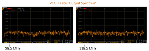
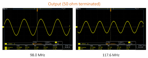
Finally, the end result was an oscillator that could be adjusted across the desired range (I used a 10 kohm variable resistor to act as a potential divider to control the varicap diodes). The output looked like this:
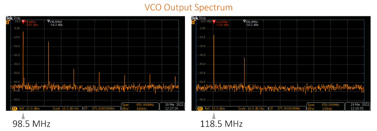
It can be seen that the output level drops as the frequency is increased, from -3 dBm at 98.5 MHz to -7 dBm at 118.5 MHz; this is a limitation of the particular topology. This might or might not be a problem for whatever the oscillator is attached to (an amplifier could be appended if needed).
A spectrum analyzer helps, but an oscilloscope can provide some insight too if a spectrum analyzer is not available. The traces below show what the output looked like at this point in the experimentation process.
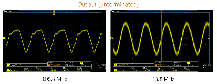
I didn’t like that the output looked so poor at the high frequency as if it was collapsing (which it did if tuned to a slightly higher frequency). At the lower frequencies, the output seemed reasonable, although the second harmonic was larger than desired.
After tweaking the component values some more, I was happier with the tuning range and the output at the higher end was better, and it could be tuned to beyond 120 MHz.
Output Spectrum Stability
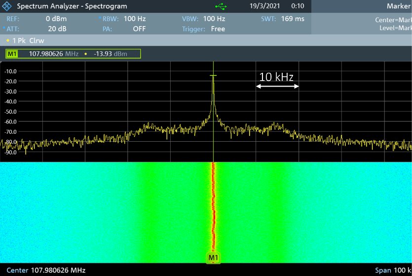
The screenshot below shows the zoomed-in spectrum across a 100 kHz span, with the VCO set for a centre frequency of about 108 MHz. (Note: the measurements in the screenshot are 10 dB lower, because I had a 10 dB attenuator wired up to the spectrum analyzer; so, the actual power was -3.9 dBm, not -13.9 dBm). The colourful spectrogram view covers about half a minute of time. The output was as expected; a knock on the table would cause the frequency to shift, due to the air core inductor construction. But left alone, it didn’t drift much at room temperature, for this short period of time.
Output Filter
An output filter has the disadvantage of expense since it would require one or two inductors, but it would improve the output enough to be worthwhile. I used free ‘Elsie’ software to compute the filter.
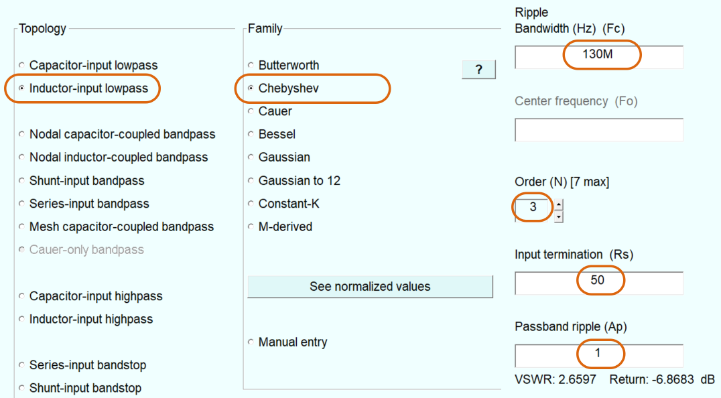
The software allows you to select the various parameters of the desired filter and then it outputs a circuit diagram (and the component values can be tweaked) and it generates a chart and tables of the response, to be uploaded into other software (such as Excel or Matlab).
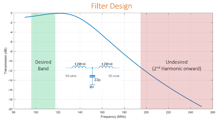
This was the result; greatly improved:
And of course, that is therefore reflected in the ‘scope traces too.
Circuit Diagram
Here’s the final circuit; the LC circuit comprises of L1 and C7, D1, and C6 all in series. The control voltage is applied through R6. Resistors R4 and R5 to ground cause the diodes to be reverse biased. The output filter is L2, L3, and C12.
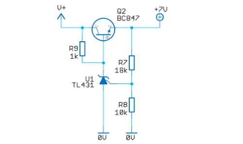
In order to have a stable output, a regulated supply is needed. I decided to build that using a TL431 circuit as shown below. I preferred that because it’s a simple low-cost way to have an adjustable supply; the voltage can be tweaked by changing a resistor, to optimize the signal output. 7V seemed to provide a reasonable output in the screenshots above. The supply input can be from 8.5V to 12V with this regulator circuit.
Using a Printed Circuit Board (PCB)
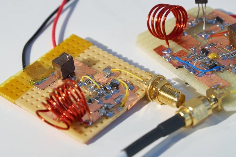
The photo here shows the prototype with some of the main components annotated.
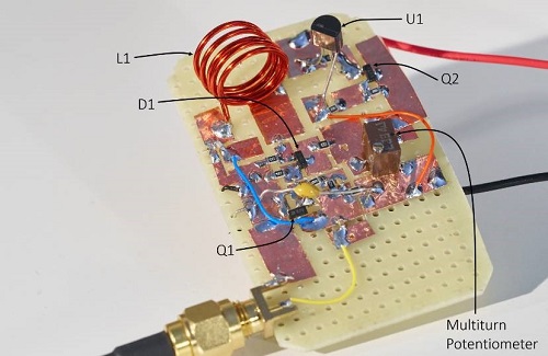
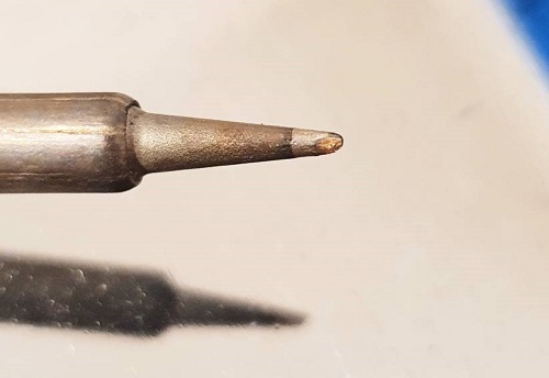
I’d built the circuit using adhesive copper tape, but I wanted to have a printed circuit board laid out so that I can more easily build up VCOs for different frequency ranges in the future. The PCB layout might not need to change for up to (say) 500 MHz or so, just the component values can be changed. For the final design, large surface-mount parts are used so that the circuit can be assembled using normal thin 0.35mm solder and tweezers hold the parts. Others may have better recommendations, but personally, I find this particular style of tweezer very effective to grip surface mount components accurately. This shape of soldering iron tip works for me:
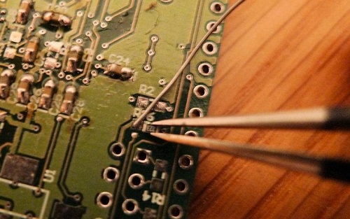
One approach is to melt the solder onto one pad first, and then re-heat it as the component is placed on it. Personally, I find it quicker to just hold the component with tweezers and the solder in one hand and bring them to the board at the same time, as shown in the photo below.
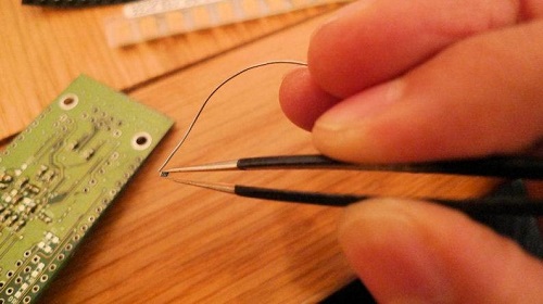
With such a method, the solder can be fine-adjusted to sit on the pad by just flexing the finger grip slightly, and then bring in the soldering iron.
This style of head magnifier works great to make everything visible! (there are lower-cost near-identical looking clones on Amazon but I have not tried them).
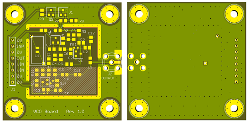
The PCB files are attached to this blog post, ready for sending to any PCB factory; it’s a low-cost 2-layer 50 x 50 mm design. I have not built the circuit using the PCB yet, so I cannot guarantee it will function, unfortunately (but I think it should work). The lower shaded portion of the board is not needed, it is a buffer that I have not tested yet (I’ll update the blog post when I do that after the board is made up). The rest of the PCB contains the circuit as shown in the schematic above. Most of the parts are 0805 sized, so this should be easy to hand-solder. For the inductor L1, the PCB has space for a hand-wound coil (it can be made to different dimensions or turns or stretch or squash it to change inductance), or for a ready-made fixed-value surface-mount inductor.
After building and testing the circuit, if desired, thin metal can be folded into a 30 x 30 mm box to solder on top to act as a shield.
Components
All of the resistors and capacitors can be 0603 or 0805 sized; both will fit the PCB. I used NP0 capacitors where possible. Three BLM18RK221SN1D or EXC3BB221H ferrite beads are used (others can be used too provided they fit; they are quite small). For the filter, suitable inductors are two 0805 sized 120nH inductors. L1 is a 210nH inductor (is optional, an air coil can be wound instead) for the LC resonant circuit. Any normal RF connector can fit the board, such as an SMA connector. For the semiconductors, Q1 is a BFR92P NPN transistor (it needs to be a high-frequency transistor, 2N2222 or 2N3904 will not work) and Q2 is a BC847 NPN transistor and D1 is a BB914 dual varicap diode. U1 is a TL431 integrated circuit.
For a shield (if required), it could be hand-made from a thin metal sheet, or alternatively, a ready-made metal frame and metal cover might fit if the fixed surface-mount inductor is used for L1 instead of the air coil.
Summary
A simple VHF voltage-controlled oscillator can easily be realized using large surface mount components. It does take some experimentation to ensure the entire desired range can be tuned and that the output is acceptable over that range (it’s worth keeping a range of capacitors handy for this – they are not wasted, if you desolder them carefully then they can be stored away for future experimentation). An output filter can help to reduce the harmonics. The output power was around -4.5 dBm to -7.5 dBm across the range.
The printed circuit board could be useful for constructing VCOs for different frequency ranges. If a fixed frequency is desired then the varicap diode and associated parts could be removed and the PCB traces bridged with a wire. The air coil inductor can be stable but may need different construction (e.g. wind around a plastic former or glue it) in order to reduce the impact when it is knocked.