The expanded availability of high speed and very high speed ADCs and digital processing is making oversampling a practical architectural approach for broadband and RF systems. Semiconductor scaling has done much to boost speeds and lower costs (in dollars, power, board areas, etc.), enabling system designers to explore different avenues of converting and processing signals either using broadband converters with flat noise spectral density, or band limited Σ-Δ converters with high dynamic range in the desired band of interest. These techniques change the way design engineers should think about signal processing, and the way they specify products.
Noise spectral density (NSD) and its distribution over the band of interest can provide insight and guide the converter selection process.


In comparing systems that operate at very different speeds or looking at how a software-defined system will handle signals of different bandwidths, noise spectral density (NSD) can be considerably more useful than signal-to-noise ratio (SNR) specifications when making comparisons. It doesn’t replace the other specifications, but is a useful item to add to one’s analysis toolbox.
How Much Noise Is in My Band of Interest?
When SNR is specified on a data converter’s data sheet, it indicates power in a full-scale signal compared to the total noise power present in all the other frequency bins.
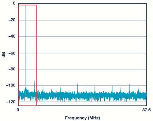
Since the signal of interest is between dc and 4 MHz, it’s relatively simple to apply digital post processing to filter out or throw away everything above 4 MHz (keeping only what is in the red box). Here, that would entail throwing away 7 ⁄8 of the noise and keeping all of the signal energy— essentially improving effective SNR by 9 dB. Stated another way, if it’s known that the signal is going to be in one half of the band, one can, in effect, throw away the other half of the band while eliminating only noise.
This leads to a useful rule of thumb: processing gain can provide an extra 3 dB/octave of SNR for oversampled signals in the presence of white noise. In the Figure 1 example, it was possible to apply this technique across 3 octaves (a factor of 8) and thus realize 9 dB of SNR improvement.
Of course, if the signal is going to be somewhere between dc and 4 MHz, it isn’t necessary to use a fast 75 MSPS ADC to capture the signal. A mere 9 MSPS or 10 MSPS would meet the Nyquist sampling theorem bandwidth requirements. In fact, it’s possible to decimate the 75 MSPS sample data by a factor of eight to produce an effective 9.375 MSPS data rate, while preserving the noise floor in the band of interest.
It is important to perform the decimation properly. Decimating by simply throwing away seven out of every eight samples would cause the noise to fold back or alias into the band of interest. In that case, there would be no SNR improvement. It’s necessary to filter first and then decimate to realize the processing gain.
Even in that case, while a perfect brick wall filter would eliminate all of the noise and yield the ideal 3 dB/octave of processing gain, no actual filter has that kind of characteristic. In practice, the amount of filter stopband rejection necessary is a function of how much processing gain is to be achieved. Also, keep in mind that the 3 dB/octave rule of thumb is based on an assumption that the noise is white. It’s a reasonable assumption in many, but not all, cases.
One important exception crops up when the dynamic range is limited by nonlinearity or other sources of spurious intermodulation products in the passband. In these cases, the filter and throw away approach may or may not catch the performance-limiting spur, and more careful frequency planning approaches may be required.
Converting SNR Sample Rate into Noise Spectral Density
When more than one signal is present in the spectrum, such as in the FM broadcast band with its myriad radio stations, the situation gets more complicated. In terms of recovering any one signal, what’s most important is not the overall noise of the data converter, but rather the amount of converter noise that falls into the band of interest. This requires digital filtering and post processing to eliminate all of the out-of-band noise.
Multiple paths can be taken to reduce the amount of noise that falls into the red box. One way is to select an ADC with a better SNR (less noise). Alternatively, using an ADC with the same SNR and a faster clock (for example, 150 MHz) will spread the noise over a broader bandwidth, leaving less noise in the red box.
NSD Enters the Picture
This raises a new question: is there a better specification than SNR for quickly comparing converters to determine performance in the red box? This is where noise spectral density enters the picture. By specifying noise in terms of spectral density (typically in dB relative to full scale per hertz of bandwidth (dBFS/Hz)), it’s possible to compare different ADCs with different sampling rates to determine which might have the lowest noise in a particular application.
Table 1 represents a data converter with 70 dB of SNR. It illustrates the improvement in NSD with sample rates from 100 MHz to 2 GHz.
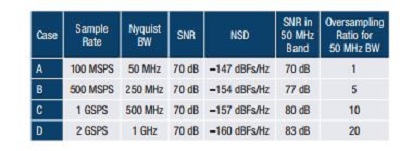
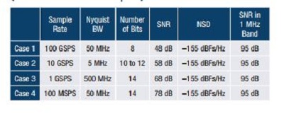
Table 2 shows several combinations of SNR and sampling rates for some very different converters. However, they all have the same NSD so that each would have the same total noise across a 1 MHz channel. Bear in mind, the actual resolution of the converter may be a much larger number than the effective number of bits, as many converters want to have extra resolution to ensure that the quantization noise has negligible contribution to the NSD.
In a conventional single-carrier system, it might seem absurd to use a 10 GSPS converter to capture a 1 MHz signal. But in a multicarrier, software-defined environment, that may be the exact course of action taken by a designer. One example might be a cable set-top box that may use a 2.7 GSPS to 3 GSPS full spectrum tuner to capture the cable signal that’s composed of hundreds of TV channels, each with a few MHz of bandwidth. For data converters, noise spectral density is conventionally specified in units of dBFS/Hz. That is, dB with respect to full scale per Hz, a relative measure. This provides a sort of output referred measurement of the noise level, or alternatively, in dBm/Hz or even dB mV/Hz, to provide a more absolute measurement—that is, input referred indication of the data converter’s noise.
SNR, full-scale voltage, input impedance, and Nyquist bandwidth can also be used to calculate an effective noise figure for an ADC. However, that’s a fairly involved calculation.
Oversampling Alternatives
Running an ADC at higher sample rates generally means higher power consumption, both in the ADC itself and in the subsequent digital processing. Table 1 illustrates the benefits of oversampling in terms of NSD, but the question remains: “is oversampling really worth it?” As Table 2 shows, it would also be possible to achieve better NSD by using a lower noise converter. A system that needs to capture multiple carriers would need to be running at a higher sample rate, so each carrier was oversampled. Nonetheless, oversampling still has a number of benefits.
Simplification of the antialias filtering—the act of sampling will alias higher frequency signals (and noise) back down into the Nyquist band of the converter. Thus, to avoid aliasing artifacts, these signals must be suppressed by a filter ahead of the ADC. This means that the filter’s transition band must fall between the highest desired capture frequency (FIN) and the alias of that frequency (FSAMPLE, FIN). As FIN approaches one half of FSAMPLE, the transition band of this antialias filter becomes very narrow, requiring a very high order filter. Oversampling by two to four substantially relieves this constraint in the analog domain, placing the onus on the relatively easier to process digital domain.
Minimizing the impact of folding converter distortion products, even with a perfect antialias filter, will result in imperfections, generating spurs and other distortion products in the ADC including some very high order harmonics. These harmonics will also fold across the sampling frequency, potentially falling back in-band and limiting SNR in the band of interest. At higher sample rates, the desired band becomes a small fraction of the Nyquist bandwidth, and therefore, reduces the folding occurrences. It’s also worth mentioning that oversampling also aids in the frequency planning for other system spurs that might fold in-band, such as device clock sources.
Processing gain affects any white noise—this includes thermal and quantization noise, along with noise from certain types of clock jitter. As higher converter and digital-processing speeds become more readily available, system designers are more frequently using some amount of oversampling to leverage these advantages, such as noise floors and FFTs.
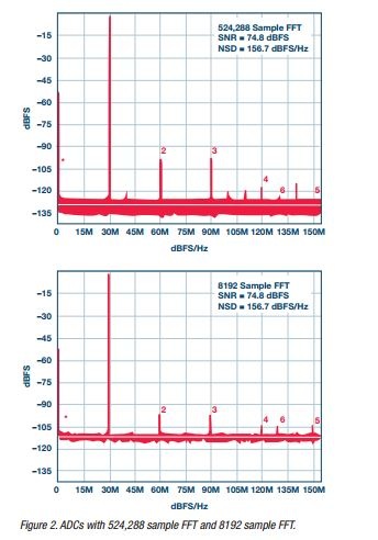
It’s tempting to compare converters by inspecting spectral plots and looking at the depth of the noise floor, as seen in Figure 2. When making such comparisons, it’s important to remember that the plotting of the spectrum depends on the size of the fast Fourier transform. Larger FFTs will break the bandwidth into more bins, accumulating less noise in each bin. In that case, the spectral plot will apparently show a lower noise floor, but this is just a plotting artifact. In fact, the noise spectral density has not changed (this would be the signal-processing equivalent of changing the resolution bandwidth of a spectrum analyzer).
In the end, floor comparisons would be acceptable if the sampling rates and FFT sizes were dentical (or scaled appropriately). If not, it could be misleading. This is where the NSD specification provides a useful direct comparison.
When the Noise Floor Isn’t Flat
So far, these discussions of processing gain and oversampling have been based on the assumption that any noise is flat across the Nyquist band of the converter. That is a reasonable approximation in many cases, but a number of situations arise where that assumption doesn’t hold up.
For example, it has already been mentioned that processing gain doesn’t really apply to spurs, though oversampled systems may offer some advantages in frequency planning and handling spurs. Besides that, 1/f noise and some types of oscillator phase noise will have spectral shaping, and processing gain calculations will not apply in such cases.
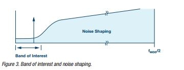
One important circumstance in which noise is not flat occurs with the use of Σ-Δ converters. Σ-Δ modulators use feedback around the quantizer to shape the quantization noise of the modulator, thus lowering the noise that falls into a band of interest at the expense of raising the noise out of band, as seen in Figure 3.
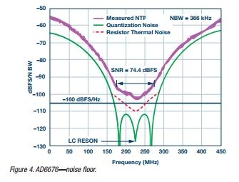
Even without a full analysis, one can see that using NSD as the specification to determine the in-band usable dynamic range is particularly helpful for Σ-Δ modulators. Figure 4 shows a zoomed in plot of the noise floor for a high speed, bandpass, Σ-Δ ADC. Across the 75 MHz band of interest (with center frequency at 225 MHz), the noise is around –160 dBFS/Hz, providing more than 74 dBFS of SNR.
Conclusion
The expanded availability of high speed and very high speed ADCs and digital processing is making oversampling a practical architectural approach for broadband and RF systems. Semiconductor scaling has done much to boost speeds and lower costs (in dollars, power, board areas, etc.), enabling the system designer to explore different avenues of converting and processing signals either using broadboand converters with flat noise spectral density or band-limited Σ-Δ converters with high dynamic range in the desired band of interest. These sorts of techniques change the way we think about signal processing and the way we
specify the products. In pondering how to capture a signal, engineers may be called upon to compare systems that may operate at very different speeds. Noise spectral density can be considerably more useful than SNR specifications making these sorts of comparisons, or looking at how a software-defined system will handle signals of different bandwidths. It does not replace the other specifications, but is a useful item to add to your specifications list.
About The Author: