


Abstract
A true bidirectional buck-boost approach for DC power backup applications provides utmost efficiency and improves overall system reliability. This approach is also ideal for optimizing battery health as the battery charge and discharge levels can be programmed as needed by the battery chemistry and according to the current health of the battery. With its inherent nature of true peak current sensing and ability to limit the average current, the high-voltage buck-boost family of products from Renesas Electronics provides a comprehensive solution for battery-powered and battery backup applications.


This article will describe how a fully hardwired standalone backup system can be designed at a lower cost using the Renesas ISL81601 controller family. This approach reduces the cost by improving battery utilization and avoiding complicated current sensing and charging circuits. The design can also be adapted to a microcontroller or host-based solution by supporting on-the-fly changes with parametric settings.
Introduction
Energy storage devices are at the core of the modern sustainable energy revolution, and the fast-emerging battery technology is helping its expansion across all industries. Li-ion batteries and supercapacitors are two major electrical energy storage devices becoming more popular in the modern world.
Market researchers estimate that demand for Li-ion batteries will double in the next seven years. At the same time, demand for other types of energy storage devices, such as supercapacitors, is also increasing. The simple charge profile and smaller size of these energy storage devices are further fueling their grow th and popularity. As a result, the use of power backup systems is spreading from conventional and critical applications to non-conventional applications such as doorbell systems and security cameras.
The use of these energy storage devices is even encroaching into markets and applications that w ere once ruled by lead acid batteries. On the other hand, the downtime cost for critical applications such as telecom systems, Internet hosting, or medical process control is so high it has become almost necessary to mandate a backup energy source.
Employing redundancy by N+1 configuration does provide backup for internal failures, but it does not compensate for power loss due to a failure of the input power source. The traditional AC uninterruptable power supply (UPS) requires a significant initial investment and wastes power as it needs to carry more power than required. An AC UPS also delivers lower overall efficiency due to multiple conversion losses. However, today’s advances in battery technology have accelerated its growth in the DC UPS arena.
A localized energy source using a battery as a power backup source provides a cost-effective and reliable redundancy to the primary source. Having a localized DC power backup for redundancy also helps with power design optimization because the power level can be estimated and matched correctly with the load current. A new energy buffer concept is being used in high-end industrial applications to provide backup on critical voltage rails.
A Typical Power Backup System and Inherent Issues
A very general battery backup system would consist of a battery at its core. The system would then add electronics for charging from a DC source and electronics for discharging to transfer the battery power to the system when the main source is not connected. Fig.1 shows a typical battery backup system. In general, the difference between the input voltage and the output voltage is larger than zero, which is one of the many reasons for lower efficiency.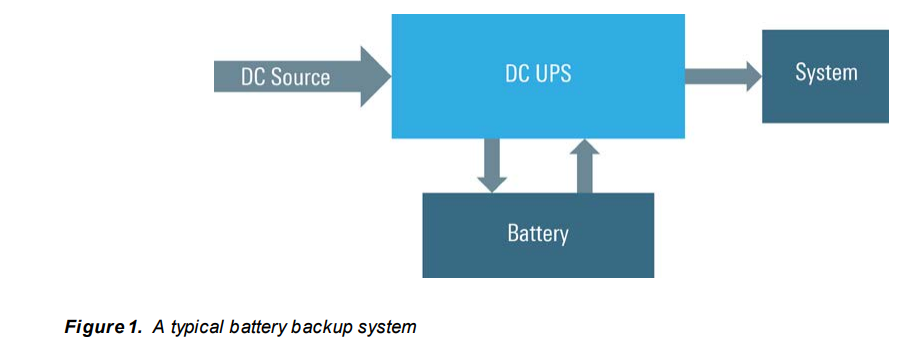
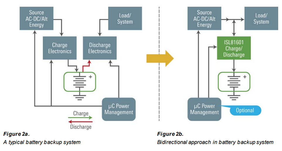
Fig.2a is a generic representation of internal blocks of a battery backup system.
A battery or other energy-storing system is used to store energy; it is charged through a charging circuit. The charging circuit can be either buck or boost, depending on the source and battery voltage. Sometimes the designer can even choose to use a simple linear regulator for charging to save some cost. A discharge circuit is normally a buck converter to power the load from the energy source by converting the battery voltage into the voltage needed by the system.
Though systems engineers have been able to make the system work, keeping it stable comes with a few inherent issues. The system is bulky, complicated, and it needs an active circuit manager along with lots of protection circuits. As the component count increases with circuit complications, the system MTBF becomes smaller. Another issue with this type of system is having the battery in the line of the source and the system, w hich means that the battery is always working whenever the system is operating. This type of arrangement affects battery life and cannot be used by many battery types.
 If we look at the system (Fig. 2a) from an efficiency perspective, these types of systems tend to be less efficient mainly due to a non-ideal duty cycle (less than 100% in buck mode and more than 0% in boost mode). Of course, there are other factors such as power topology used, components selected, and switching frequency that affect the efficiency, but the difference in Vin and Vout voltage harms the efficiency most. In general, if all other factors are constant, efficiency decreases as the gap between the input and output voltage increases. For example, a 12V to 3.3V power conversion will have lower efficiency than a 12V to 5V conversion.
The impact of the voltage difference between input and output voltage on how it affects the converter’s efficiency can be described as follow s. The efficiency of a buck converter increases with the duty cycle and peaks at 100% duty cycle. Similarly, the efficiency of a boost converter increases with a decrease in the duty cycle and is maximized when the duty cycle is 0%
In a boost and buck approach for a DC power backup system, an input voltage such as 12V is used to charge a higher voltage battery, normally 24V or 36V, and then a buck converter is used to convert the battery voltage back to 12V. These types of systems also carry similar issues and are less efficient due to non-optimal duty cycles in both conversions.
To overcome this obvious efficiency issue, some designers have proposed applying a higher duty-cycle buck converter by using a battery voltage that is close to the required system voltage. In this boost-buck approach, a boost circuit is used to charge the battery to a slightly higher voltage, and a simple buck converter with a higher duty cycle is used to deliver system voltage at a higher efficiency and lower cost. The overall cost of the power components is lower when the same components are used for both charging and discharging using a microcontroller.
However, the above approach has a major disadvantage due to lower utilization of battery capacity. In this system, the battery is not allowed to discharge below the system voltage; hence, a larger capacity battery is required, with the battery being one of the costliest elements in the system. This approach also means that the battery always stays in a high-charge state, affecting the overall battery life.
In short, it can be said that these battery backup architectures tend to be complicated, inefficient, and are not reliable.
These issues can be resolved to improve overall system performance if a true bidirectional circuit is implemented. A true bidirectional system would be able to remove numerous complications and significantly improve system reliability. See Fig. 2b.
A Bidirectional Approach for Battery Backup
A bidirectional approach using a true bidirectional controller such as the ISL81601 or ISL81401 brings multiple advantages into a DC power backup system or a battery-operated application. First, it simplifies the design and improves overall reliability by merging the complicated architecture of charging and discharging into one circuit. Having separate charging and discharging circuits would require two inductors (assuming a switching converter is being used to maximize the efficiency for both stages), while the bidirectional approach would need only one inductor. With the bidirectional approach, the same set of electronics changes its current direction to accommodate both charging and discharging. A bidirectional buck-boost controller solution significantly improves the system’s overall efficiency as the battery or storage element voltage can be brought closer to the system voltage. As the battery and system voltage is positioned closer, the converter would always operate at a duty cycle that maximizes efficiency. At the same time, the system will have the ability to discharge the battery deeper when necessary; thus, improving the battery capacity utilization.
In a buck-boost converter-based design, the battery voltage and the required system voltage can be kept the same. Another trade-off that can be exploited is battery health. In this approach, the battery charge and discharge levels can be programmed to suit the battery health.
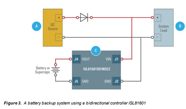
Fig. 3 shows a simple setup for bidirectional operation. A DC source “A” is connected to a load “B”, and the same source is connected to a battery or supercapacitor through a bidirectional buck-boost converter “C.”
The battery voltage rating can be any voltage that matches the converter’s voltage rating
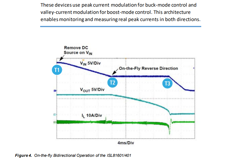
 The Renesas ISL81601/401 is a true bidirectional buck-boost controller with inherent peak current sensing and monitoring at both ends. These devices use peak current modulation for buck-mode control and valley-current modulation for boost-mode control. These devices also feature a cycle-by-cycle negative peak inductor current limit to protect the system when operating in reverse direction. The current-carrying direction can be changed through hardwired settings or through a microcontroller with proper interface circuitry. This makes the DC power backup designs simple and efficient, and provides significant savings in terms of size and bill of materials (BOM) costs
Fig. 4 shows the DC power backup operation waveforms. A 12V battery is used along with an adjustable DC source for easy explanation. As the DC source voltage is changed from 18V to 9V, the battery takes over and starts sourcing the required current into the system. Just before time T1, the source voltage is 18V, and it is feeding the load and battery. Once the battery is fully charged, the source is removed at time T1. At T2, the converter’s set point is reached, and it reverses its current direction to discharge the battery and stop the system voltage from falling below 9V. At T3, the battery or supercapacitor is completely exhausted, which in turn, pulls the power dow n. With that process, it gives the system enough time to shutdown systematically. The source is switched and the current direction is changed at T2 without any noticeable disturbances.
 Renesas Bidirectional Buck-boost Controllers
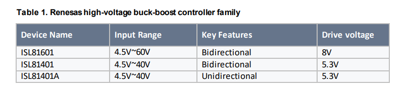
As a leading power management IC supplier, Renesas has both bidirectional and unidirectional buck-boost controllers for different application and customer needs.
The ISL81601/ISL81401 product family from Renesas Electronics consists of true bidirectional 4-sw itch buck-boost controllers that boast an impressive list of cost- and time-saving features such as frequency dithering and external bias. Its proprietary architecture ensures peak inductor current is monitored and measured at both ends. It also has two current monitoring pins to monitor both input and output currents that can be used for constant current (CC) and constant voltage (CV) control and other system management cases.
The inherent behavior of this architecture provides very robust protection from any failures on either side of the system. It has four independent control loops for controlling input voltage, output voltage, input current, and output current. This gives the designer complete and independent control over input and output voltage and current settings, which becomes very useful in DC power backup applications as charging and discharging is normally done at a different rate.
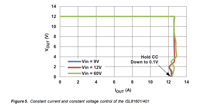
Peak current sensing at both ends and the cycle-by-cycle current limit of this product family ensures high operational reliability by providing instant current limit in a fast-transient condition at both input and output ends. Their CC operation down to a very low voltage avoids a runaway condition in the event of overload or short circuit. Fig. 5 shows CV/CC control of these controllers.
 The ISL81601/401 measures and tracks the duty cycle continuously for mode conversion and moves into one-cycle buck and one-cycle boost operation in buck-boost mode. Fig. 5a show s a standard buck-boost circuit using the ISL81601, and Fig. 5b show s key switching waveforms during buck-boost mode operation.
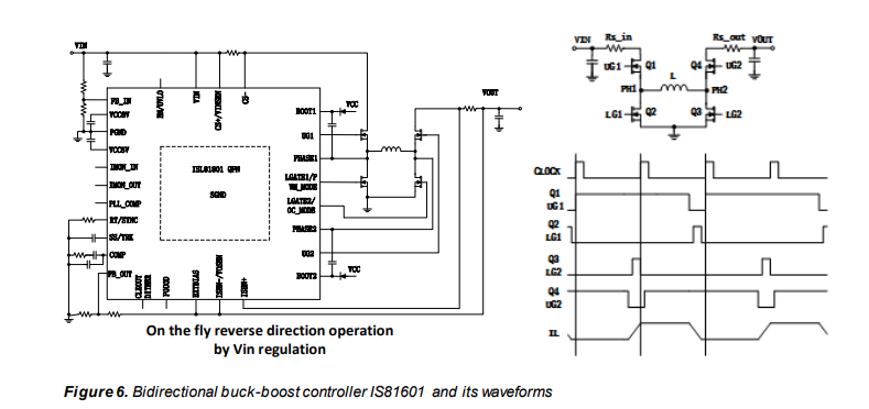
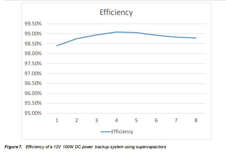
This architecture also ensures a cycle-by-cycle buck-to-boost operation change and vice versa on every clock signal, resulting in robust control during buck-boost mode operation. Notice the inductor current waveform of Fig. 6. Its frequency is half of the clock frequency, resulting in higher efficiency. Fig. 7 shows the efficiency percentage for a 12V 100W design using supercapacitors.
 Other notable features of this family of products includes:
- High-voltage operation – Covers most of the battery voltages used today
- Bidirectional operation – Reduced PCB space and overall cost savings • Proprietary modulation scheme – Lowest ripple and smoothest mode transition
- On-the-fly operation – µC friendly
- Constant current (CC) and constant voltage (CV) operation – Supports battery charging; eliminates many external components
- Multilayer over-current protection – Robust operation
- External Bias – Minimizes power losses, better efficiency
- Light-load efficiency mode –Greater efficiency; longer battery life
- Extensive fault protection – Robust and reliable operation
- Frequency synchronization – Common frequency operation; lower EMI
- Frequency dithering – Lower EMI
- Input and output current monitoring – Improved system control
- Current sharing and cascade interleaving – Scalable design
Design Tools from Renesas
Evaluation Board/User Guide:
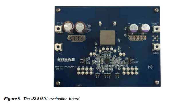
An evaluation board and detailed user guide for customer testing and evaluation are available for the ISL81601. A photograph of the evaluation board is shown in Figure 8. Additional details can be obtained through the following link.
https://www.renesas.com/us/en/products/software-tools/boards-and-kits.html
PowerCompass Multi-load Configurator
The PowerCompass tool helps users quickly identify parts that match their specific requirements, set up multiple rails, perform high-level system analysis, and generate custom reference design files. The tool is available exclusively as a web app from which users can also work offline.
iSim Design and Simulation Tool
Renesas provides a web-based power simulation tool called iSim, which is an easy-to-use, interactive power management and op-amp design tool. iSim allow s the user to quickly select supporting components and design and simulate their circuit and system.
Courtesy: www.renesas.com