


With the advent of smaller and smarter integrated circuits (ICs) in automotive electrical systems, it’s time to start addressing the elephant in the room: Why are we still controlling motors in sunroof modules, window lifts, power locks, tailgate lifts, memory seats, compressors and pumps with relays? Sure, relays are cheap and simple to design with, but their functionality is limited to the point that they now seem cumbersome for modern motor applications given their limited lifetime and large solution size. For a quiet, small and safe solution, a solid-state IC is the best option for automotive motor-control applications.
Solution size


Let’s compare the two solutions, both shown in Figure 1: a typical relay solution and an equivalent solid-state solution with the same voltage and current rating.
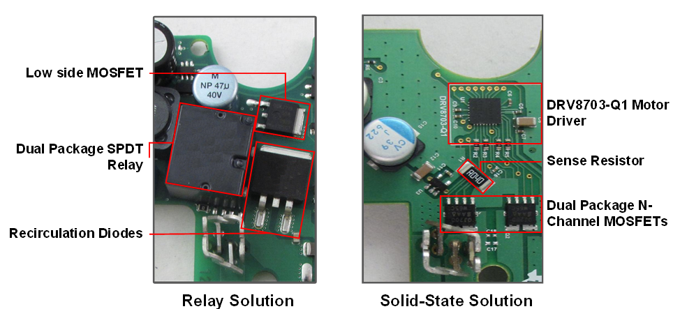
Focusing just on solution size, the solid-state 8mm-by-8mm quad flat no-lead (QFN) plus two dual-package N-channel metal-oxide semiconductor field-effect transistors (MOSFETs) is about one-third the board area of the relay solution. Looking at the z-axis, the entire solid-state solution is approximately .9 mm tall. or 0.035 inches. If you want to build a motor driver printed circuit board (PCB) that cleanly fits on the back of your motor housing, TI’s solid-state solution is well suited for this application.
Other than size, solid-state gate drivers also integrate a whole suite of protection features that would otherwise have to be built discretely in a relay solution. These features include:
Motor current measurement
For any type of current regulation, both the relay and solid-state systems require a shunt resistor. A relay solution requires a separate discrete amplifier circuit to increase the voltage measured across a sense resistor. That increased voltage is then sent to a microcontroller’s (MCU) analog-to-digital converter (ADC) so that the digital logic in the MCU can make decisions on when to shut-off the motor or limit the current. But a solid-state motor driver typically integrates the low-side current shunt amplifier, so the only discrete component you need is a single current-sense resistor. Figure 2 shows the differences between an integrated motor-drive IC and discrete current-measurement circuit topologies.
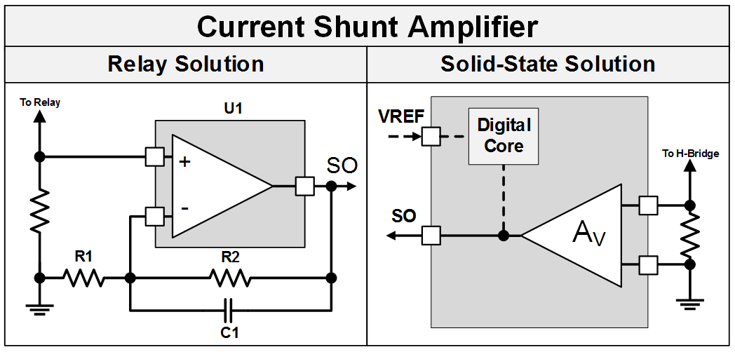
TI’s motor drivers took current regulation a step further and integrated a cycle-by-cycle current-chopping method using an internal comparator tied to the output of the integrated current-sense amplifier. All that’s needed is an external voltage reference and the device will handle the current limiting, freeing up resources that would otherwise be used on an MCU or built discretely. While the output of the sense amplifier still ties to a package pin, if you just need some level of current regulation, consider a fully- integrated solution, like the DRV8702-Q1 or DRV8703-Q1.
Interfacing to the MCU
When interfacing the relay and solid-state solutions to an MCU, solid-state ICs typically enable a direct connection between an MCU general-purpose input output (GPIO) and analog-to-digital converter (ADC) pins. These ICs are generally flexible enough to interface with 1.8, 3.3 or 5V logic-level voltages with a high-impedance pull-down resistor referenced to ground. To achieve a similar type of input control for a relay solution, some sort of current gain needs to control the solenoid coil inside of the relay. Figure 3 shows the difference in circuit topologies when interfacing relay and solid-state drivers with an MCU.
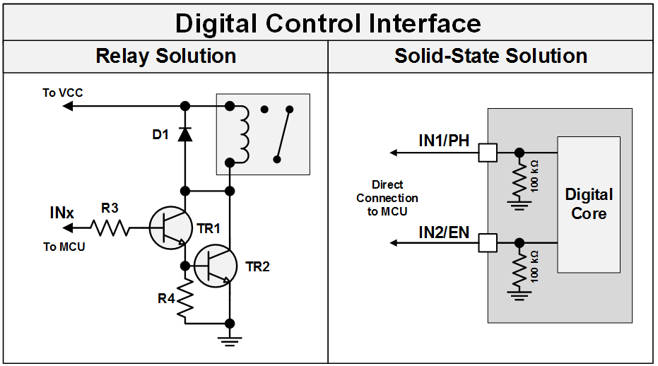
The relay solution in Figure 3 outlines the need for a Darlington-pair of N-doped P-doped N-doped (NPN) bipolar junction transistors (BJTs), two resistors and a protection diode all just to interface a relay coil directly with an MCU GPIO pin. In order to create an H-Bridge and drive a bi-directional motor two dual-package single-pole double-throw [SPDT] relays would be required, meaning twice the circuit components outlined above are needed to drive both relay coils independently. Using one of TI’s motor drivers allows for all of these discrete components to be removed, creating a much smaller and cleaner PCB solution.
Motor-speed profiles
Motor-speed profiles with relays are incredibly inefficient. Designers can implement multi speed control schemes for power windows, lift gates, sunroofs, sliding doors or pumps with relays, using different-sized resistors placed in series with the motor, or a motor that has multiple windings for different speeds. Both of these solutions require more relays if you want to select different speeds, and with more relays comes more board space and discrete components.
Using a solid-state solution, you only need to provide TI’s motor drivers with two pulse-width modulations (PWM) signals coming from an MCU to control your motor speed. On the DRV8702-Q1 and DRV8703-Q1, TI offers a phase/enable mode, where only a single PWM signal is applied to the enable pin and a simple logic high-or-low phase pin controls the direction of the motor. The logic-level PWM signal is directly translated to the MOSFET gate with the correct voltage to fully enhance the high- or low-side MOSFET. Using this type of interface, you can quickly design multi speed pumps, custom motion-profiles for sliding glass sunroofs, soft-close power windows, cheap variable-speed windshield wipers, or any other type of simple motion-controlled motor application.
Show me the proof
The Small-Footprint Sunroof Motor Module Reference Design is a solid-state motor-control module intended for the sunroof and window-lift applications. This TI reference design uses the DRV8703-Q1 gate driver with an integrated current-shunt amplifier alongside two dual-package automotive-qualified MOSFETs to create a very small power-stage layout compared to typical relay solutions. The design also includes two of TI’s DRV5013-Q1 latching hall sensors to encode the motor position.
Designing motor control systems using one of TI’s solid-state motor drivers will help reduce the size of a PCB solution, allowing for more and more motors to be controlled from the same module. With our motor drivers’ high-level of integration and simplistic control scheme, designers can quickly and easily redesign most modern brushed-DC motor controller circuits that are currently utilizing relays.
Article Courtesy: e2e.ti.com