What is time? Everybody knows what it is, but it is hard to explain what it is to someone else. The opening sentence in the Wikipedia entry for time isn’t bad – “Time is the indefinite continued progress of existence and events that occur in an apparently irreversible succession from the past, through the present, into the future.”
This blog is on the importance of time in functional safety and avoids all of the philosophical issues and doesn’t require a knowledge of general or special relativity.


There are more uses of time in the various standards than I had realized, and I didn’t get to cover them all, but I think I got the most important ones. Hopefully this might serve as a useful summary of issues and terminology around time in functional safety standards.

Figure 1 – my Snapchat Bitmoji thinking about this blog with apologies to Salvador Dalí
Let’s start with a typical safety-related system according to IEC 61508. The picture below shows EUC (equipment under control) and a non-safety EUC control system at the top. At the bottom however is the E/E/PE (electrical electronic or programmable electronic) control system which monitors the EUC using sensors and has the ability to take the EUC to a safe state if the sensors detect a problem. For instance, if the EUC is a large spinning motor controlled by a variable speed drive the E/E/PE safety related system might monitor the speed of motor and if a safe speed limit is exceeded it will take the system to the a safe state which is typically (unless it’s a flying airplane) to stop the motor spinning.
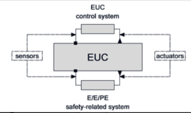
Figure 2 – equipment under control
Process safety time is defined in part 4 of IEC 61508 as the “period of time between a failure, that has the potential to give rise to a hazardous event, occurring in the EUC or EUC control system and the time by which action has to be completed in the EUC to prevent the hazardous event occurring.” We could immediately get bogged down by discussing what is a hazardous event but I won’t.
Lets continue with the spinning motor example, the figure blow shows a motor spinning at an increasing speed until at time t1 it exceeds a set safe speed limit. The E/E/PE safety-related system detects this out of limit events and initiates STO (safe torque off as defined in IEC 61800-5-2) to bring the motor to a stop by time t2. The time t2-t1 must be less than the process safety time, which from the figure it is (we even have a bit of margin built in for less effective braking as the years go by and the equipment wears).
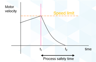
Figure 3 – process safety time from IEC 61508
Determining the process safety time can be difficult in some cases but in other cases it is fairly easy to calculate once you make certain conservative assumptions. For instance suppose we have a robot safety application where the robot is not in a cage and if somebody approaches the robot has to be stopped before a person can reach the system and incur harm. In that case if we know the maximum speed of the robot, the maximum assumed walking speed of an operator (generally taken as 1.6m/s in machine safety standards), the braking time of the robot, how long it takes the safety function to respond to the limit being broken we can define a process safety time. Below is one example of the calculation based on ISO TS 15066 soon to be incorporated in ISO 10218-2.
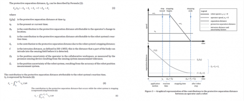
Figure 4 – calculating the process safety time for a robot using SLS safety function
In the case of robot safety the process safety time is used to define a protective separation distance which is then monitored with a laser scanner or perhaps in the future a 3D TOF camera (a 3D TOF camera may allow the protective separation distance (and it follows the process safety time) to be reduced because it doesn’t have to allow for reach over).
Another very similar aspect of time is shown below. However here it is a fault which occurs within the E/E/PE control system itself rather than an external bad event which triggers the move to the safe state. This fault should be detected by diagnostics within the E/E/PE safety related control system. If the diagnostic to detect this fault is run every tdiagnostic_test_interval then worst case the fault will not be detected until the indicated time. From there it will take a period of time to achieve the safe state which is given in this figure as the “fault reaction time”. In the graphic the sum of the diagnostic test interval and the fault reaction time is shown as the safety response time and once again the safety response time needs to be less than the process safety time. For high demand mode (demands at a rate exceeding once a year there is an alternative option to have the diagnostic test > 100x the demand rate).
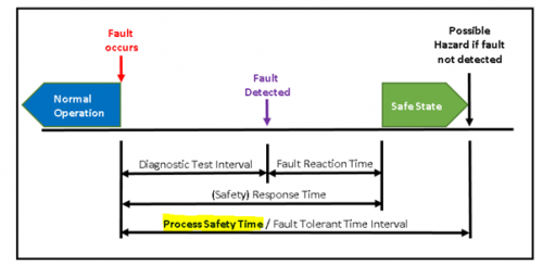
Figure 5 – time related to diagnostics
I won’t get distracted, but the above calculation really only applies to single channel architectures because with a two-channel architecture the second channel is still available to take you to the safe state and so the diagnostic test interval is not so important. For machinery the EU Vertical recommendations for use however require that a diagnostic test interval of at least once per year for SIL 2/PL d and once per month for SIL 3/PL e. For all the automotive guys reading this blog please remember than in industrial, unlike automotive, a safety system might turn on and run for 20 or 30 years without ever turning off. There is no nice time like key-on to test for latent faults.
Of the terms above only process safety time is defined IEC 61508 and the diagnostic test interval is used in the text of IEC 61508. The fault reaction time is actually used in IEC 61800-5-2 but not mentioned in IEC 61508 where it states things like “the sum of the diagnostic test interval and the time to perform the specified action to achieve or maintain a safe state is less than the process time”. Fault reaction time I believe is a good term.
Also shown above is FTTI (fault tolerant time interval) which is actually a term from ISO 26262 but is similar to the process safety time from IEC 61508. Other terms from ISO26262 are FDTI (fault detection time interval) which is similar to the diagnostic test interval shown above and FHTI (fault handling time interval) which is what is shown above as the safety response time. It’s a pity standards could not standardize on such terms based on electropeida or similar.
For networks the term safety function response time is given as shown below and is similar to the response time shown in the graphic above. It reminds us that the maximum possible transmission time from one end of the network to the other needs to be considered. Note the sum is always done with the maximum guaranteed response time rather than an RMS sum. The justification for this might make another future blog. A nice sentence from IEC 61784-3 is “Empirical measurements may only serve as a plausibility check of the worst-case calculation” which makes it clear it must be done by analysis rather than measurement.
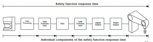
Figure 6 – a graphic from IEC 61784-3 to illustrate safety function response time
Another important time concept within IEC 61508 is the demand rate. A rate is the inverse of time. So for instance if you have something that happens once per hour the demand rate is 1/h. For something that happens every 15 minutes the demand rate is 4/h. If something happens once per year the demand rate is 1e-4/h. If the estimated demand rate is less than 1/year then according to IEC 61508 we use PFD (probability of failure on demand) as the key reliability metric but if the demand rate is greater than once/year the key metric is PFH(average probability of failure per hour). The allowed PFH and PFD vary depending on the required SIL (safety integrity level). I show the SIL dependent requirement below for the PFH because the units are 1/h and so related to time.
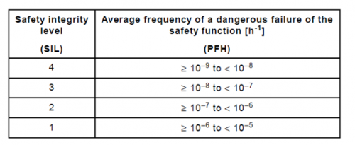
Figure 7 – maximum allowed PFH per SIL from IEC 61508 part 1
Why we switch from PFD to PFH at a demand rate of once/year is an interesting topic and would make a good future blog, however I won’t get into it today.
Another concept within IEC 61508 is mission time. This is the expected lifetime of the safety system. For industrial applications the mission time is often 20 years. The useful life of the components used to build the safety system needs to be greater than the mission time or otherwise you will enter the wear-out period of the components and the components reliability will quickly degrade(you can cope with this by replacing the components before that happens). For automotive the mission time might be 15 years (not a bad lifetime for a car) but that might be only 6 months of operating time (6 months is approx. 5000 hours at 30 miles/50 kilometres per hour means you would have 150000 miles or 2500000 km on the clock) which sounds about right for cars in Ireland at least.
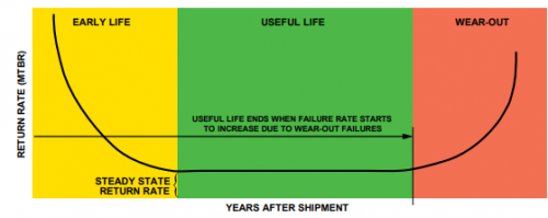
Figure 8 – Reliability bathtub curve from the ADI reliability handbook
Speaking of reliability for electronic components the reliability is often expressed as a FIT (failure in time) which is the number of failures expected in 1 billion hours of operation. A typical FIT for an IC might be 20 FIT but simple components can claim a FIT of 1. A FIT of 1 does not mean that a component will last for a billion years but rather that within the green area of the curve above the probability of failure for every hour of operation is 1e-9/h. One reason for using FIT is that people feel better working with numbers such as 10 rather than 1e-8.
The reliability of a component is often represented by the symbol λ. An alternative expression of reliability is MTTF (mean time to failure) and MTTF is very common within machine safety standards. MTTF typically taken as 1/λ if you are operating in the flat portion of the bathtub curve. The FIT and MTTF for all released ADI products based on HTOL(high temperature operating life testing- an accelerated test) can be found at www.analog.com/ReliabilityData.
An interesting equation giving the fraction of units which will still be operating correctly after a time t for a constant failure rate λ is R(t)=1-exp(-λt). After time MTTF 63% of your units will already have failed (R(MTTF)=1-exp (-1)). MTBF – mean time before failure – is generally used instead of MTTF for repairable systems. For mechanic components a β10d is used instead of MTTF. This represents the number of cycles at which 10% of the components are expected to have failed dangerously.
Another time mentioned within IEC 61508 is the proof test interval. A proof test is similar to a diagnostic but normal diagnostics are automatically run and a proof test is a non-automatic test which often involves taking the safety system out of its circuit and running tests designed to find all the failure modes of the item that the normal automatic diagnostics don’t detect. If proof testing is not allowed then it is often stated that the proof test internal is equal to the mission time. If the proof test is not perfect then if failures occur they will exist on average for T1/2 where T1 is the proof test interval or mission time whichever is shorter.
Related to the mission time is the mission profile. This is often expressed at the amount of time at a given temperature across the lifetime of a product. For instance if the lifetime is 20 years then a mission profile might be 1 year at -20’c, 4 years at 0’c, 10 years at 45’c, 4 years at 65’c and 1 year at 85’c. This mission profile can be used for reliability predictions according to standards such as IEC 62380.
As regards schedules safety should take priority over time. Dilbert gets it.

Figure 9 – Dilbert realizes the importance of time