


Many operators are currently supporting 5G in existing sub 2.5 GHz bands using dynamic spectrum sharing (DSS). DSS technology allocates spectrum resources between LTE and 5G technologies in an LTE frame structure and is often implemented with a software update to existing LTE radios and antennas. These network deployments usually implement traditional base station and antenna architectures with RF cable feed between the two components. For this reason, tower crews must implement comprehensive RF cable testing during 5G network deployment and installation and maintenance (I&M).
Many mobile operators continue to deploy multi-band, multibeam massive MIMO hybrid antennas. These antennas are fed by RF cables from the radio. Some networks use a single hybrid antenna with at least 16 RF connectors and cables feeding it. To achieve published network KPIs, the cables must be low loss and all connectors, bends and clamping brackets formed and installed correctly.


When installing new LTE or 5G base stations that include RF cable feeds to the antenna installation tower crews need to be certain that the overall system is performing to specification. Four measurements are typically used to verify base station operation. In this post, we will go into detail on each.
Modulation Quality
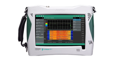
Modulation quality of LTE base stations is most commonly performed from an RF test port on the radio. Field technicians can use an instrument, such as the Anritsu Field Master Pro MS2090A (figure 1), with built-in measurements for occupied bandwidth (OBW), channel power, error vector magnitude (EVM), RSRP, and other modulation quality metrics. It is recommended that these measurements be made before the base station is connected to the antenna system.
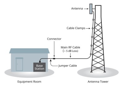
Many 5G base stations do not have an RF test port. For this reason, over-the-air (OTA) measurements must be made. Certain field spectrum analyzers offer a comprehensive suite of modulation quality measurements. It is important for field technicians to connect the base station to the antenna via a long RF cable to the tower or via short jumper cables from a rooftop-mounted base station to the antenna when testing OTA.
Cable and Antenna Measurements
Many 5G base stations are being deployed at existing LTE sites. Each tower has a loading factor that defines the maximum weight of the radios and antennas that can be mounted. Due to legacy hardware on the tower, the radio may be required to be installed at ground level and only the antenna is tower mounted.
As the RF signal travels through the cable some energy will be dissipated in the cable and connectors. A cable insertion loss measurement must be made during installation to confirm that the loss is within specification. Low-loss cables must be used to minimize the base station power and maximize efficiency. Cables with larger diameters have less insertion loss and better power handling capabilities than smaller diameter cables but are more expensive and much heavier.
It is also important to measure the magnitude of any RF reflections in the cable and antenna system. Loss of efficiency can be caused by distortion from cable and antenna feed reflections due to the power being reflected back towards the base station. Common causes of reflections are:
- Poorly installed connectors that are loose or not correctly torqued
- Connectors that have degraded over time due to weather damage
- RF cable damage (i.e. over-tightening cable clamps and bend radius causing kinks)
- Damaged and/or incorrect antennas
Cable loss and return loss are measured as swept frequency traces across the full operating band of the antenna. Connectors that have not been torqued to the correct value can result in a narrow band “suck outs” with very high insertion loss. It is important to sweep the full operating band to find such failures and recognize that cable loss has an effect on measured return loss.
Figure 2 highlights how cable loss alters the measured antenna performance. The antenna has a return loss of 15 dB but the 5 dB insertion loss improves the perceived system return loss by 10 dB. Even though this is something system engineers consider when establishing site specifications, it is important to be aware of the effects the insertion loss and cable return loss can have on the overall system return loss.
A very good system return loss is not always a guarantee of a correctly installed antenna. A faulty cable with too much insertion loss or an antenna out of specification can be the cause. The result is a larger than expected signal drop. A great portion of the signal is reflected once it reaches the antenna since the match is worse than expected. The transmitted signal is lower and the coverage from the base station is reduced.
Return loss/VSWR measurement characterizes the performance of the overall system. If either is failing, field technicians need to conduct a distance-to-fault (DTF) measurement to troubleshoot the system and locate the fault’s exact location. It is important to understand that the DTF measurement is strictly a troubleshooting tool, as well as to compare relative data and monitor changes over time to identify faults and measure cable length. A DTF measurement sweeps the cable in the frequency domain and applies an Inverse Fast Fourier Transform (IFFT) to convert results from the frequency domain to the time domain.
The Field Master Pro MS2090A integrated with the Site Master S331P cable and antenna analyzer accessory is ideal for performing line sweep measurements in the field. Return loss, cable loss, and DTF can all be made with a single instrument.
Cell Site Coverage
A coverage map for the surrounding area is required to validate that base station coverage meets the planner’s modelling when it is brought online. The MS2090A supports downloading digital maps directly from the Internet to display on the instrument screen. Plotting a channel power measurement onto the digital map using colour to represent relative strength provides a graphical and easy-to-interpret overview of the cell site coverage.
EMF Measurements
Operators of cellular networks often need to reassure the local community that the total radiated power from a new cell site base station installation is not harmful. Regulators and standards bodies such as the Federal Communications Commission (FCC) and International Commission on Non-Ionizing Radiation Protection (ICNIRP) define limits for RF field strength guaranteeing that they are safe for the general public, and for technicians working in the industry. EMF measurements need to be made to ensure the sites are compliant with the regulatory bodies’ requirements.
Courtesy: Anritsu