


Using a DMM on fixed ranges can be frustrating, but this simple design idea allows current monitoring from μA to over 100mA in a single range.
This Design Idea has proved as useful and simple. With just three or four components, it allows the monitoring of current from μA to over 100mA in a single range.


I was developing a PIC-based board and needed to monitor the current it drew from a pair of AA cells. Although spending most of its time asleep, with the boost converter’s 30μA quiescent current dominating consumption, the board could cycle rapidly through bursts of sensing, displaying and transmitting, drawing from 8mA to 100mA. Trying to use a DMM on fixed ranges was frustrating, while auto-ranging just gave me a headache owing to the fast cycling times and short on-periods. Thus, the following approach suggested itself.
The voltage across a diode increases as the logarithm of the current flowing through it, as defined by the diode equation: IF ≅ I0 • exp (eVF/kT) where IF is the forward current I0 is the reverse saturation current e is the electron charge (1.602 × 10⁻¹⁹ C) VF is the forward voltage T is the temperature (K) k is Boltzmann’s constant (1.380 × 10⁻²³ J/K).
(This is a slightly stripped-down engineer’s version; for the full works and useful links, see Shockley diode equation.) For our purposes, we can extract from it:
VF ∝ logIF at a given temperature.
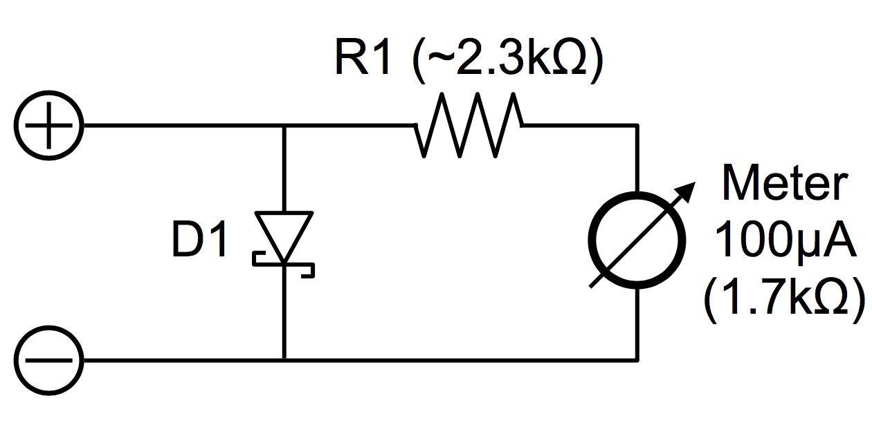
Shunt diode
Now, shunt a diode with a meter movement. At very low currents, it will indicate microamps as the current flows through it rather than the diode, while at high currents it will show the voltage across the diode and thus the log of the current (think of the diode as an adaptive shunt). Thus, the bottom of the meter scale is reasonably linear, the top is adequately logarithmic, the middle is transitional, while the whole is very useful.
Using a Schottky rectifier, a 100μA/1.7kΩ meter and a suitable series resistor as shown in Figure 1 allows the monitoring of currents from 10μA to over 100mA in a single range, with the speed of indication being limited only by the meter’s ballistics.
Anything this simple usually has more problems than components! Apart from a fiddly calibration procedure (more below), this circuit has two main flaws: its series voltage drop and its temperature stability. The diode will drop up to 400mV, so use new or fully-charged cells when monitoring or your UUT may see the battery as low. Alternatively, think of this as a handy low-battery-sense-testing feature, perhaps adding a shorting switch.