


Power distribution within a chip relies on feeding every transistor that is accomplished through the utilization of metal layers. With the new advancement of modern technology, the wires responsible for distributing power have been shrinking in size while the physical dimensions of chips have remained relatively unchanged. Remarkably, despite these changes, the overall power consumed by chips has remained relatively constant.
Moreover, as the current or power flows through a resistor, the voltage drops – this is called an IR Drop.


In this article, we will be discussing IR Drop in VLSI, types of IR Drop and EM.
What is the IR drop in VLSI?
IR Drop in VLSI is known as an “Intermediate Resistance Drop” at “Very Large Scale Integration”. It refers to the variation in electrical potential between the two ends of a conducting wire when current flows through it. This potential difference is determined by the voltage drop across a resistance, which can be calculated by multiplying the current (I) passing through the resistance by its resistance value (R).
The problems caused by IR Drops are:
- Decreased performance.
- Increased Power Consumption
According to Ohm’s Law, the IR Drops formula is:
V (Voltage) = I (Current) X R (Resistance)
Note: To avoid this, it is important to consider the problems of IR Drop during the design of the VLSI system.
The calculation required in IR Drop:
- Average Current Through Each Strap=Istrapavg=(Itotal)/(2*Nstraps)mA
- Appropriate IR Drop At The Center Of The Strap=Vdrop or IRdrop
=IstrapAvg*Rs*(W/2)*(1/Wstrap)
- Number of Straps between Two Power Pads
Nstrappinspace=Dpadspacing/Lspace.
MIN Ring Width = wring = Ip/Rj Microm
The IR Drops have two types:
- Static IR Drop
- Dynamic IR Drop
Static IR drop in VLSI
Static IR drop in VLSI refers to the average voltage drop experienced within a VLSI design. This voltage drop is influenced by the RC network of the power grid and plays a crucial role in establishing connections between the power supply and the individual cells.
The magnitude of the average voltage drop is determined by various factors, including the time period and one significant contributor to static IR drop is the gate-channel leakage current.
The formula for calculating:
Vstatic drop= lavy x Rwire (lavy is refer to leakage currents)
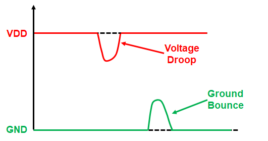
Dynamic IR drop in VLSI
Dynamic IR drop in VLSI is dropping in the voltage because of the high switching activity of transistors. The drop happens when the demand for current increases in power supply. It happens due to switching activities within the chip. Moreover, it evaluates the IR drop occurred when a large number of circuitry switches at the same time. Hence causing peak current demand.
It depends on:
- Switching time of the logic.
- Less dependent on the clock period.
Note: IR Drop in VLSI occurs specifically when there is a heightened requirement for current from the power supply, which is triggered by the switching activities of the chip.
The formula for calculating:
Vdynamic_drop = L (di/dt) [L is due to switching current]
EM and IR Drop in VLSI
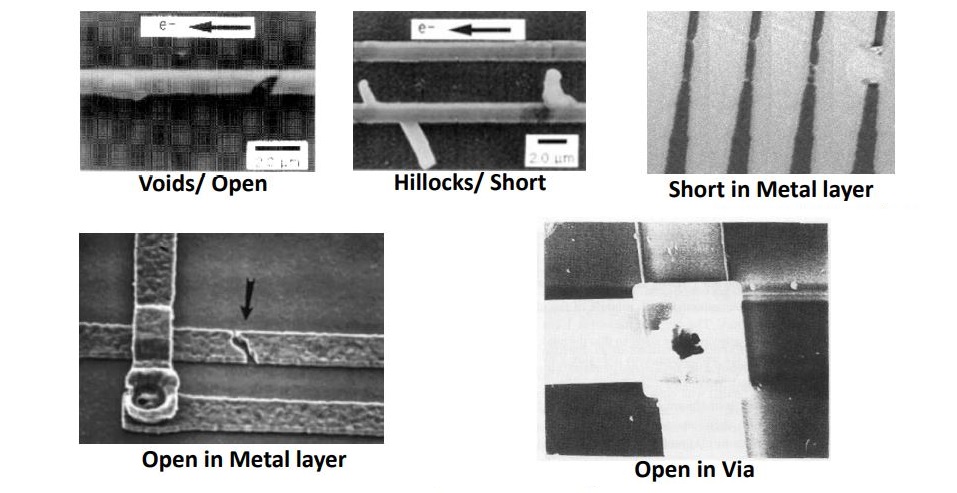
The gradual displacement of metal atoms in a semiconductor is called Electromigration. EM occurs when the current density is high enough to cause the drift of metal ions in the direction of the electron flow and is characterised by the ion flux density.
Whereas IR drop intensifies in the presence of Electromigration.
EM depends on:
- Magnitude of Forces
- Nature of the conductor
- Crystal Size
- Interface and grain boundary Chemistry
- Magnitude of Forces
- Current Density
- Temperature
- Mechanical Stress
Techniques to prevent EM and IR Drop:
With EM effects, the chances of metal wire bursting into open and shorts are high. As EM increases the wire resistance, causes dropping in voltage. Hence, this will let the device slow down or can cause permanent failure in circuits.
EM Mitigation:
- Use NDR (Non-default Rule) on the vulnerable nets (Violated nets). EM Violation is based on two parameters such as driver strength and load.
- Restrict the load target for nets.
IR Drop Mitigation
-
Using of Padding Clock Sells
Electromigration (EM) induces a phenomenon where the downstream interconnects in a circuit experience narrowing, while the upstream interconnects and vias undergo metal deposition. This effect of EM results in both the creation and disruption of connections, leading to changes in the resistance of interconnects and vias.
How to reduce IR drop in VLSI
IR drop in VLSI can be reduced by various methods:
- Add more stripes
- Using of Logic in congested areas
- Usage of Low-Power Cells
- Adding Vias
- Clock gating
- CTS Structure (minimizes clock buffers in clock tree)
- Usage of proper width of metal according to Current density
- More parallel metal wire strips
- Add buffers, if the length of the wire is too long
- Avoiding Jogs
How to fix IR drop in VLSI
Every Company has their ways of analysing the IR Drop and based on that the precaution has been taken care of.
The two most important tools for IR analysis used in industry are:
- RedHawk of Ansys
- Voltus of Cadence Design System
As per the analysis, there are numerous techniques to fix the IR Drop. Some of them are mentioned below:
- Increase in the number of De-cap cells that will boost the power delivery network.
- Reconstructing the power delivery network, if it was not built properly.
- Increases the width of the metal stripes which will decrease the separation between them.
- Spreading accurately the logic cells in a region so that the load can be distributed.
How to fix static IR drop in VLSI
When the cells switch the drop independently is calculated with the help of wire resistance. The ways to fix the Static IR Drop in VLSI:
- Increases the wire Width
- Increasing the quantity of a number of wires.
How to fix dynamic IR drop in VLSI
The formula for calculating the Dynamic drop happens with the help of switching off the cells. Ways to fix Dynamic IR Drop:
- Using Dcap cells in between wires.
- Increase in the number of straps.
To conclude,
As the technology node is contracting, it leads to decreases in the geometries of the metal layers and the resistance of the wire. Hence, this lead to power supply voltage during CTS, the buffers and inverters which were added along the clock path to balance the skew.
IR drop shows the voltage drop on the current and these issues are highly common. With various techniques and measures, these issues can prevent and also reduce electromigration in lower geometry chip designs.