

“The production line has gotten bigger and the company needs to extend the transmis-sion distance of the high-speed interface from the monitoring camera.” “A high-speed wireless interface would be nice so that a small terminal can be detached from the per-manently mounted sensor.” “The surveillance system has to be converted to fiber optics so that an area up to 1 km away can be monitored.” These and similar demands are often heard, showing the need for an interface to use in industrial applications, with OA equipment, and by security/monitoring systems. This is largely due to easier-to-use cameras with CMOS image sensors and to the increasing number of ways of observing many viewpoints with a variety of evolving technologies that enable IoT (the Internet of Things).
Easy-to-use transceiver


THine Electronics has already developed and begun sales of the THCS251 transceiver IC, which can meet these demands rather simply. THine Electronics calls this product a serial transceiver or an 8b/10b transceiver.
This serial transceiver IC combines both a transmitter and receiver on one chip. A pair of IC’s can be connected with just two pairs of differential lines, one as an uplink and the other as a downlink (Diagram 1).
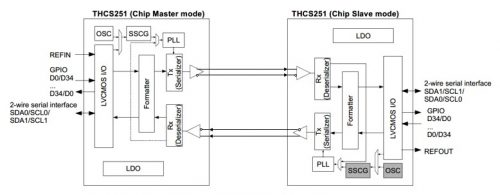
Diagram 1: A transmission system using THCS251’s
This chip can transmit up to 4.67Gb/s over an uplink and a downlink, which is pretty fast. For a frame rate of 30 frames/s, you can send a full HD (1920 × 1080 pixels) video. In short, this transceiver can move data along the uplink and the downlink at the same time because it uses full-duplex rather than half-duplex communication, which uses one transmission line to transmit/receive data in turns.
How then do we use this IC? It also provides a parallel I/O port with a 35-bit data width, handles 12-bit image and control signals for a camera, and even works with I2C bus signals. This means that the transceiver can process high-speed image signals, low-speed control signals, or I2C bus signals ̶ the built-in serializer (an 8b/10b encoder circuit) will auto-matically serialize the data and transmit/receive using two pairs of differential lines.
All the user has to do is to set up the end terminal. Absolutely no software development is needed at all. To top it all off, you only need two serial transceiver IC’s. You just need to install these on each board that you want to use bi-directional data transfer. There is no need for any other external IC’s.
Using these serial transceiver IC’s will extend the range of bidirectional data commu-nications by 15 m or more. Changing a system using the IC to fiber optics or wireless is pretty simple as well. Attach a fiber optic transceiver module to the back of the serial transceiver IC for the Master side and to the front for the Slave side to convert to fiber optics. To change to wireless, follow the same procedure except with wireless communication modules.
Transceiver IC’s everyone would’ve thought existed
Transceiver IC’s can reduce the number of connecting wires in a long-distance system, extend the transmission distance, convert to fiber optics and wireless easily, and utilize bidirectional data communication…. This item does not use a particularly high level of technology, only the 8b/10b encoder/decoder that has been around for years. Yet there has been no product with the same features in practical use. THine Electronics thinks there are two possible reasons for this.
One reason is that conventional transceiver IC’s, transmitter IC’s, and receiver IC’s had specific target applications, a strong characteristic of ASSP (Application Specific Standard Product), so there was really no concept of a multi-purpose transceiver IC like the one that THine has just released.
The other reason is that most developers put their major concern on reducing the number of transmission lines. However, half-duplex communication has required one pair of differential lines (two transmission lines), and full-duplex communication needed two pairs of differential lines (four transmission lines). This is why half-duplex communication with fewer transmission lines has been traditionally preferred and is now in use. However, half-duplex communication has some issues ̶ converting to fiber optic or wireless is dif-ficult, and low-speed control signals are hard to transmit in real time. So what THine Electronics did was to prioritize solving these issues, and not reducing transmission lines this time.
It used to require lots of effort and time
Of course, the need to reduce the number of lines, extending the transmission range, and converting to fiber optics/wireless for bidirectional data transmission has always been there. This is nothing new. Then how did THine Electronics meet these demands?
There were two ways. One is to use an FPGA. If you use an FPGA, you can accommodate practically any need, but it involves designing hardware and software. To extend the transmission distance of bidirectional data communication, an FPGA would entail devel-oping hardware such as a protocol-processing circuit and a physical layer circuit as well as software that can set inputs/outputs and process scrambling. Furthermore, transmitting data over a long distance requires an equalizer function to be implemented in either hardware or software. Each of these tasks would take a lot of effort and a long time.
The other way to meet these demands is to use commercially available off-the-shelf chips that are compatible with the high-speed interface. For example, THine Electronics offers two transmitter IC’s and two receiver IC’s that are compatible with “V-by-One HS” and meet the demands mentioned above can be met (see Diagram 2(a)). Specifically, one transmitter IC and one receiver IC are implemented on each Master and Slave side, con-nected by two pairs of differential lines. With this setup, you can transmit video signals and control signals in full-duplex mode.
You will not be able to transmit I2C bus signals over these lines, but there is the option to utilize a device that operates as a Sub-Link (one pair of differential lines) and is compatible with low-speed bidirectional data communication. However, the Sub-Link operates only in half-duplex mode, which means that it can extend the transmission range but cannot be easily converted to fiber optics or wireless transmission (see Diagram 2(b)). Therefore, this second method does not entirely meet the requirements.
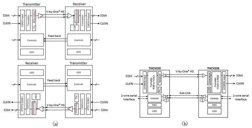
Diagram 2: System configuration using transmitter IC’s and receiver IC’s compatible with “V-by-One HS”
It should be mentioned that analog semiconductor manufacturers other than THine Electronics make transmitter and receiver IC’s that meet the requirements for bidirectional data communication. These products are all pretty much the same and they all have the same issues.
Other than these options, there is a way to use a transceiver IC compatible with low-speed transmission. With this option, just like with THCS251, you just need to implement one chip each to the Master and Slave side. However, the data transmission speed is only about 1 Mb/s, which is too slow to transmit video signals. This option again will not meet user demands.
Demonstrations of extending transmission range are prepared
THine Electronics has prepared demonstrations that will show everyone the utility of the THCS251 serial transceiver. Let us introduce one of them.
This is a demonstration for an FA use. A camera is attached to the tip of the robot arm and an operator far away controls it remotely while watching the camera feed (Image 3). The THCS251 has been implemented on both the Master and Slave side boards. The boards are connected with two pairs of differential lines (a total of four transmission lines) (Diagram 4)
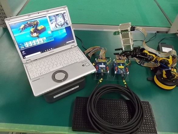
Image 3: Demonstration
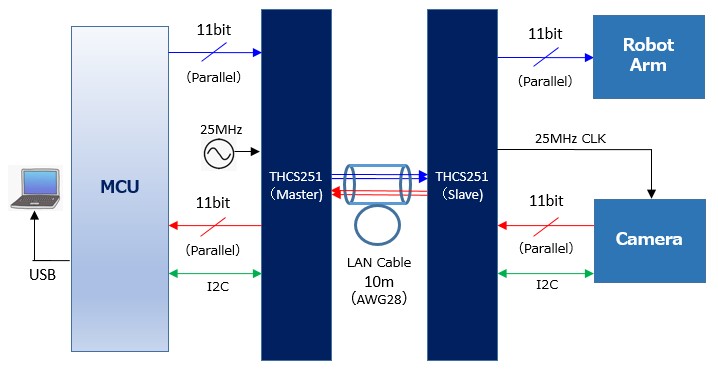
Diagram 3: System configuration
The Slave board is connected to the robot arm. Video signals from the camera are seri-alized in the THCS251, and then transmitted to the Master board via one pair of differential lines (the downlink). On the Master board, video signals are received by its THCS251, deserialized, and then transmitted to the PC via a microcontroller board (an Arduino board) to display the video feed on the monitor.
Next, the operator, judging that the robot arm needs to be moved, enters the required control command to the software on the PC. These control signals are sent to the micro-controller board via a USB interface, converted into I2C signals, transmitted to the Master board, and then input to the THCS251. After that, the signals are transmitted to the THCS251 on the Slave board via one pair of differential lines (the uplink), deserialized, and then input to the drive controller of the robot arm. This is how the robot arm is controlled.
In the demonstration, the Master and Slave boards are connected by a 10 m cable. Be-cause full-duplex communication is possible even with a 10 m cable, the control signals sent by the PC can be transmitted to the robot arm almost in real time and the arm movement can be controlled. This enables real-time adjustment of the robot arm from a distance simply by watching the video.