


Abstract
Is RF engineering a form of black magic? This article analyzes the challenges faced in the development of ADH519S, an 18 GHz to 31 GHz low noise amplifier (LNA), for the aerospace market. The die used in the product development for space was originally released to the commercial industry in the LC4 package. To release this product for the space and high-reliability market, and comply with MIL-PRF-38535 standards, this part was assembled using the most suitable and available hermetically sealed ceramic package. This article presents a unique solution and process education to improve RF performance via bonding. This product development process presented the following challenges:
- The most suitable and available space-qualified hermetically sealed ceramic package had a large cavity in relation to the die in the originally released package. The larger cavity drove the need to double the length of bond wires, which, when combined with the parasitics of the new package, had the potential ato cause device instability.
- Even if instability did not occur, the parasitics of the long bond wires could degrade the S-parameters.
This article reviews the different methods used to overcome these challenges and how to achieve the best stability and noise figure performance from the new hermetically sealed ceramic package.


Project Description and Design
In an effort to achieve improved stability and noise figure across the specified 18 GHz to 31 GHz frequency range, a 0 dB passive attenuator was integrated into the package to shorten the RF in/out bond wire length.
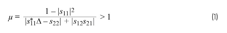
Four different types of circuit configurations were built during the engineering phase and compared in terms of critical parameters of an LNA, which includes stability, S-parameters, and noise figure. The Mu (µ) stability factor was used to measure and compare stability, as shown in Equation 1. The magnitude of µ is a measure of stability. The larger the µ factor, the more stable the device will be.
The four LNA engineering types are:
Eng1
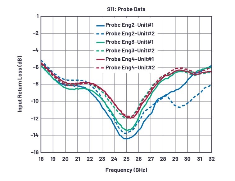
The LNA die was simply positioned in the center of the package and wire-bonded with double round bond wires. As expected, due to package parasitics and bond wires, the µ stability factor across the specified operating frequency range was less than 1 and even close to 1 at some frequencies. To achieve stability across the frequency range, improvement was needed for the input return loss (S11). This would require reducing the parasitics to the input of the LNA. This resulted in the development of Eng2.
Eng2
To improve the stability, a 0 dB attenuator was added to the input of the LNA. Adding the attenuator at the LNA input improves the input matching, resulting in improved input return loss (S11). As a result, bond wires were also shortened, which contributed to reduced parasitics.
Input return loss was improved, but as a result of the current and thermal noise of the attenuator passive components, the noise figure did not meet specifications for this device. To improve the noise figure, configurations Eng3 and Eng4 were designed and evaluated.
Eng3 and Eng4
In both circuit types, the attenuator was placed at the output of the LNA die to improve the noise figure. Based on the Friis cascaded noise figure equation, the first stage contributes most to total noise, and introduced noise to the following stages is divided by gain of previous stages. As a result, input noise becomes less significant. In this configuration, the total noise figure is defined as:
![]()
Where FT is the total noise figure, FLNA is the LNA noise figure, FATTN is the noise figure of the attenuator, and GLNA is the gain of the LNA. There is also a possible trade-off of gain reduction due to the loss in the passive component attenuator following the amplifier stage.
In engineering sample Eng3, ribbon bonds were used for die-to-die bonding as well as RF in/out bonds. In contrast, sample Eng4 LNA and attenuator dies were wire-bonded with double round bond wires. Simulations (using ADS) of the two bond options using ribbon vs. double round revealed only slightly improved input return loss and gain using the ribbon bonds for die-to-die bonding. Therefore, to confirm the simulations, both types were assembled and evaluated.
Comparing Results from Different LNA Bonding Configurations
Eng3 and Eng4 vs. Eng2
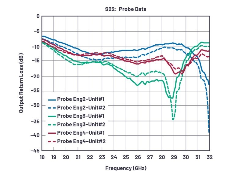
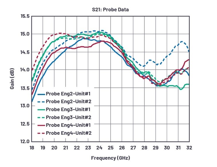
Having the attenuator at the output improves the output return loss (S22) because the signal reflections are minimized due to impedance matching. This in turn improves matching at the output and consequently results in better output return loss. The expected trade-off of having lower gain was evident for lower frequencies, but in frequencies greater than 22 GHz gain response (S21) was almost equal and even better in one Eng2 sample, which can be justified by unit-to-unit variations.
Eng3 vs. Eng4
When comparing ribbon wire bonds vs. double round bond wire samples, Eng3 had better performance across the frequency range as a result of lesser skin effect and crosstalk in ribbon bonds. Since ribbon bond has a larger surface area compared to its cross section, they have a lower resistance and therefore more power efficiency. Test results showed the ribbon bonded samples had a slightly better gain performance and almost equal or negligibly improved input return loss, and had a significantly better output return loss than double round bonds.
LNA Performance Plots
Figure 1 through Figure 4 illustrate S-parameters for two units of configuration for Eng2, Eng3, and Eng4. This data is obtained by probing the packaged devices. It was determined at the beginning of the evaluation of bonding options for this part that Eng1 would not be considered since simulations revealed that the configuration would prove to be the most unstable.
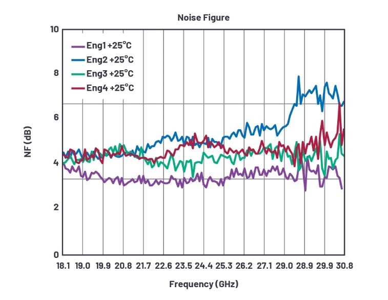
The noise figure test data shown in Figure 5 is measured on an evaluation board.

Conclusion
RF engineering, the so-called black magic, is just a series of predictable physics rules.
Below is a summary of unlocking this magic for the LNA described in this article:
- For LNAs where matching and return loss is a concern due to parasitics, including an attenuator in the package cavity is an excellent method for reducing parasitics and improving return loss. However, the following trade-offs should be considered:
- Attenuator at input: increases noise figure
- Attenuator at the output: lowers the gain
- Reducing parasitics by strategically placing the attenuator inside the package also improves S-parameters, which can be used as a measurement of stability using the µ factor, and overall helps in achieving nonconditional stability across the frequency range.
- In super high frequency (3 GHz < SHF < 30 GHz) operations, ribbon bonds have better performance compared to round wires. The trade-off would be the complexity of assembly where manufacturability needs to be considered.
It is important to note that these results could have been predicted based on fundamental RF rules and formulas. However, before assembling the different device types, simulations were run for the two die placements and different bondings in ADS and Genesys. The empirical results of the evaluations confirmed the simulations.