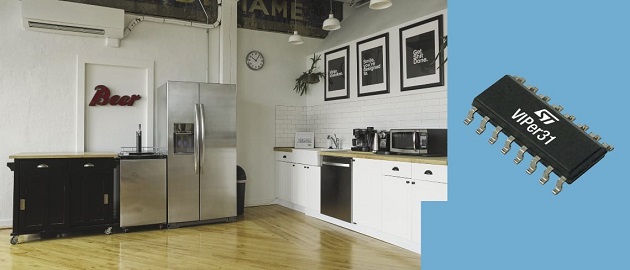
VIPER31 is the first ST high-voltage converter to offer up to 18 watts in a fly-back topology with a universal input mains range (85–265 VAC). Despite a relatively recent launch, it is already in a popular metering system and multiple appliances. As a result, we expect to sell more than one million units in 2021. This positive response is due to its 800 volts avalanche rugged power MOSFET and advanced controller features. Indeed, thanks to its architecture, the VIPer31 is flexible, robust, and efficient. It was thus essential to understand what the new high-voltage converter means to engineers.
Meet the New Family
The VIPER line covers a wide range of applications, as we recently saw with the VIPER26K. The VIPERx1 family tailors to flyback topologies with both primary-side and secondary-side regulation as well as buck. Put simply, we traditionally find this device in switched-mode power supplies (SMPS) that do not have an optocoupler. The VIPER01 had an output power of 4 W, and the VIPER11 hovered around 8 W. The 18 W of the VIPer31 is thus a significant step forward. The new product also has a lower maximum RDS(on) of 3.5 Ω. Comparatively, the VIPER01 has an RDS(on) of 30 Ω while the VIPER11 sits at 15 Ω.
There are currently eight part numbers under the VIPer31 series, with more on the way. The VIPER317 has a drain current limit protection (IDLIM) of 710 mA. The VIPER318 has an IDLIM of 850 mA, and the VIPER319 reaches 990 mA. There are also X, L, and H variants for these versions. The X type has a jittered switching frequency (Fosc) of 30 kHz ± 7%. The L type has a Fosc of 60 kHz ± 7%, and the ones marked H are at 132 kHz ±7%. Choosing the right oscillator frequency (Fosc) allows engineers to select more cost-effective EMI filters and reduce their bill of materials.
VIPER31: Flexibility
600 mA in buck topology
When engineers choose a component, they must often explain their rationale. And there’s no easier way to outline a thought process than to show it in action. Hence, we are coming up with multiple development boards, including the STEVAL-VP319X1B. This platform is highly symbolic because it’s the first time a VIPER product can address a buck converter with a load current (IOUT) of 600 mA. Experts understand that it is rare today to reach such a high load current with a high-voltage buck converter. Such development boards thus emphasize the device’s characteristics and show how engineers can take advantage of it.
Trans-Conductance Error Amplifier
Professionals may face another dilemma: justifying the qualification of a new device when their company works on a vast range of products. The upcoming STEVAL-VP318L1F and STEVAL-VP319X1B can help decision-makers with less technical knowledge. The VIPER31 has a transconductance error amplifier with 1.2 V ± 2% reference voltage. As a result, engineers can use the device more than fly-back topologies with primary-side regulation and non-isolated flyback with direct resistive feedback. As mentioned, the STEVAL-VP319X1B implements a buck converter, whereas the STEVAL-VP318L1F is a fly-back converter with secondary-side regulation that would work great in air conditioners. Finally, the STEVAL-VP318L2F is an 18 W isolated flyback with primary-side regulation.Hence, its error amplifier allows the VIPER31 to address the most common topologies, thus allowing the qualification of one family of devices for a wide range of products.
Wide Input Voltage Range

It is increasingly common for ODMs to develop a design in one country before exporting it to the rest of the world. Engineers must, therefore, show that they took international standards into account. Unfortunately, a large majority of the industry ships high-voltage converters with a narrow range of input voltages. Hence, engineers can help explain why they selected the VIPER31 by pointing to its wide range of voltage input that extends from 85 V to 265 V.
Designers may also struggle with the inherent complexities of specific applications. Smart meters, smart home systems, air conditioning units, or emergency lighting networks offer a unique challenge. They must deal with a loss of power at the grid that forces a universal power supply to take over. In this instance, the final product must still be functional even if the input voltage drops at much lower levels than usual. Engineers can thus find comfort in the fact that the VIPER31 has a drain-source startup voltage of only 24 V. Moreover, we ensured that these features are easily demonstrable. Professionals can take the upcoming STEVAL-VP319X1B, change capacitors C1 and C2, and enjoy the lower nominal starting input voltage.
VIPER31: Robustness and Efficiency
Undervoltage and Overvoltage Protection
Consumers pay increasing attention to the safety and robustness of their products. Hence, teams often ask how power devices can help make their designs more reliable. For instance, engineers looking to build air conditioners are sensitive to these issues because a malfunction can have a severe human cost. Designers also know that their company will be more receptive to features like the undervoltage (UVP) and overvoltage protection (OVP) of the VIPER31. Since each has a dedicated pin, it’s possible to use the UVP pin to disable the IC or the entire SMPS, and the internal threshold is typically 0.4 V. The OVP disables the pulse-width modulator even after the auto-restart and only resumes switching once the OVP condition expires. The VIPER31 also comes with overload protection and thermal shutdown. These features explain why we used an SO16N package with more pins than the SSOP10 of the VIPER01 and VIPER11.
Better and Fewer External Components
Engineers also struggle with cost issues because a component has many direct and indirect consequences. The price of the part itself is a critical element of the equation. However, one high-voltage converter will dictate what active and passive components will influence the overall BOM. Hence, when designers try to explain why they chose a VIPER31, very often, they point to its pulse skipping feature, which allows them to choose smaller inductors while protecting magnetic components from current peaks. Similarly, the variants with different oscillator frequency will ensure designs have a more cost-effective EMI filter. Finally, the current limitation is now precise enough in the VIPER31 that external components are no longer necessary.
Ready for Low-Power MCUs and Energy Efficient Systems
The cost considerations are also increasingly complex because of consumers’ awareness. Buyers are more sensitive than ever about a purchase’s impact on the environment and their utility bill. The best way to answer these demands is to choose a component that suits low-power systems. For instance, the VIPER31 has an Error Amplifier reference voltage of 1.2 V to generate 3.3 V for MCUs easily. The ST converter also has a quiescent current below 350 µA, thus achieving 10 mW of power consumption in standby. Hence, engineers can take pride that even under the most stressful conditions, their designs offer significant power savings.
For more information, visit blog.st.com


