and AC driven permanent magnet synchronous motors (PMSMs) can deliver the required precision,)
The need for precise motion control is growing across applications such as robotics, drones, medical devices, and industrial systems. Brushless DC motors (BLDCs) and AC driven permanent magnet synchronous motors (PMSMs) can deliver the required precision, while also meeting the need for high efficiency in a compact form factor. However, unlike brushed DC motors and AC induction motors, which are easy to connect up and run, BLDCs and PMSMs are much more complex.
For example, techniques such as sensorless vector control (also called field-oriented control, or FOC), in particular, offers excellent efficiency together with the advantage of eliminating the sensor hardware, thereby reducing costs and improving reliability. The problem for designers is that sensorless vector control is complicated to implement, so its use can extend development times, adding cost and possibly missing time-to-market windows.


To solve this dilemma, designers can turn to development platforms and evaluation boards that already have the sensorless vector control software baked in, enabling them to focus on system design issues and not get bogged down in the nuances of coding the control software. In addition, these development environments include all of the motor controller and power management hardware integrated into a complete system, speeding time to market.
This article briefly describes some of the needs for precision motion control and reviews the differences between brushed DC, AC induction, BLDC and PMSMs. It then summarizes the basics of vector control before introducing several platforms and evaluation boards from Texas Instruments, Infineon Technologies and Renesas Electronics, along with design guidance that facilitates the development of precision motion control systems.
Examples of precision motion control applications
Drones are complex motion control systems and typically employ four or more motors. Precise and coordinated motion control is needed to enable a drone to hover, climb, or descend (Figure 1).
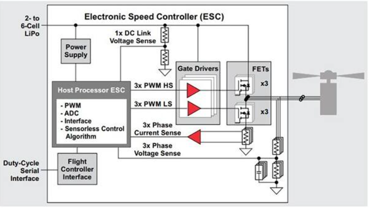
Figure 1: Drones typically use four or more motors, typically BLDCs or PMSMs, spinning at 12,000 revolutions per minute (RPM) or higher, and are driven by an electronic speed controller (ESC). This example shows an ESC module in a drone using a brushless motor with sensorless control. (Image source: Texas Instruments)
To hover, the net thrust of the rotors pushing the drone up must be balanced and exactly equal to the gravitational force pulling it down. By equally increasing the thrust (speed) of the rotors, the drone can climb straight up. Conversely, decreasing the rotor thrust causes the drone to descend. In addition, there’s yaw (spinning the drone), pitch (flying the drone forward or backward) and roll (flying the drone to the left or right).
Precise and repetitive motion is one of the features of many robotics applications. A stationary multi-axis industrial robot has to deliver different amounts of force in three dimensions in order to move objects of varying weights (Figure 2). Motors inside the robot supply variable speed and torque (rotational force) at precise points, which the robot’s controller uses to coordinate motion along different axes for exact speed and positioning.
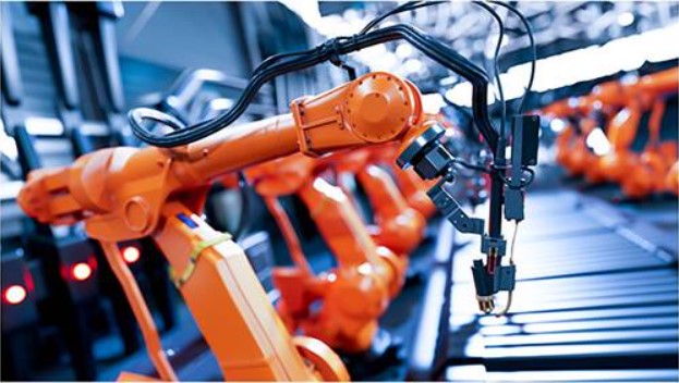
Figure 2: A stationary multi-axis industrial robot has to deliver different amounts of force in three dimensions in order to move objects of varying weights and coordinate its activities with other robots on the assembly line. (Image source: Texas Instruments)
In the case of wheeled mobile robots, a precise differential drive system can be used to control both the speed and direction of motion. Two motors are used to provide motion along with one or two caster wheel(s) to balance the load. The two motors are driven at different speeds to achieve rotation and changes in direction, while the same speed for both motors results in straight line motion, either forward or backward. While the motor controllers are more complex when compared with a conventional steering system, this approach is more precise, mechanically simpler, and therefore more reliable.
Motor choices
Basic DC motors and AC induction motors are relatively inexpensive and simple to drive. They are widely used in a broad array of applications from vacuum cleaners to industrial machinery, cranes and elevators. However, while they are inexpensive and easy to drive, they cannot provide the precision operation required by applications such as robotics, drones, medical devices, and precision industrial equipment.
A simple brushed DC motor generates torque by mechanically switching the direction of current in coordination with rotation using a commutator and brushes. Shortcomings of brushed DC motors include the need for maintenance due to wear of the brushes and the generation of electrical and mechanical noise. A pulse-width-modulation (PWM) drive can be used to control the speed of rotation, but precision control and high efficiency are difficult due to the inherently mechanical nature of brushed DC motors.
A BLDC eliminates the commutator and brushes of brushed DC motors, and depending on how the stators are wound, it can also be a PMSM. The stator coils are wound trapezoidally in a BLDC motor, and the back electromotive force (EMF) produced has a trapezoidal wave form, while PMSM stators are wound sinusoidally and produce a sinusoidal back EMF (Ebemf) (Figure 3).
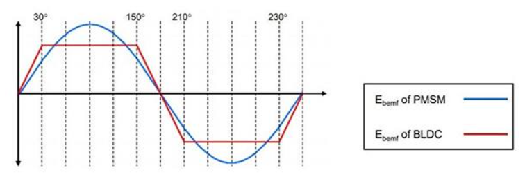
Figure 3: A PMSM motor generates a sinusoidal Ebemf, while a BLDC generates a trapezoidal Ebemf wave. (Image source: Texas Instruments)
Torque in BLDC and PMSM motors is a function of current and back EMF. BLDC motors are driven with square wave current while PMSM motors are driven with sinusoidal current.
BLDC motor features:
- Easier to control with six-step square wave DC currents
- Produces significant torque ripple
- Are lower cost and performance than PMSMs
- Can be implemented with Hall effect sensors or with sensorless control
PMSM features:
- More complex control using three-phase sinusoidal PWM
- No torque ripple
- Higher efficiency, torque and cost than BLDC
- Can be implemented with shaft encoder or with sensorless control
What is vector control?
Vector control is a variable-frequency motor drive control method in which the stator currents of a three-phase electric motor are identified as two orthogonal components that can be visualized with a vector. One component defines the magnetic flux of the motor, the other the torque. At the core of the vector control algorithm are two mathematical transforms: the Clarke transform modifies a three-phase system to a two-coordinate system, while the Park transform converts two-phase stationary system vectors to rotating system vectors and their inverse.
Use of the Clarke and Park transforms bring the stator currents that can be controlled into the rotor domain. Doing this allows a motor control system to determine the voltages that should be supplied to the stator to maximize the torque under dynamically changing loads.
High-performance speed and/or position control requires real-time and precise knowledge of rotor shaft position and velocity in order to synchronize the phase excitation pulses to the rotor position. This information has typically been supplied by sensors such as absolute encoders and magnetic resolvers attached to the shaft of the motor. These sensors have several system disadvantages: lower reliability, susceptibility to noise, more cost and weight, and higher complexity. Sensorless vector control eliminates the need for speed/position sensors.
High-performance microprocessors and digital signal processors (DSPs) enable modern and efficient control theory to be embodied in advanced system modeling, ensuring optimal power and control efficiency for any real-time motor system. It is expected that as a result of the increasing computational power and declining costs of microprocessors and DSPs, sensorless control will almost universally displace sensored vector control, as well as simple but lower performance single-variable scalar volts-per-hertz (V/f) control.
Driving three-phase PMSM and BLDC motors for industrial and consumer robotics
To get around the complexity of vector control, designers can use ready-made evaluation boards. For example, the DRV8301-69M-KIT from Texas Instruments is a DIMM100 controlCARD-based motherboard evaluation module that designers can use to develop three-phase PMSM/BLDC motor drive solutions (Figure 4). It includes the DRV8301 three-phase gate driver with dual current shunt amplifiers and a buck regulator, and an InstaSPIN-enabled Piccolo TMS320F28069M microcontroller (MCU) board.
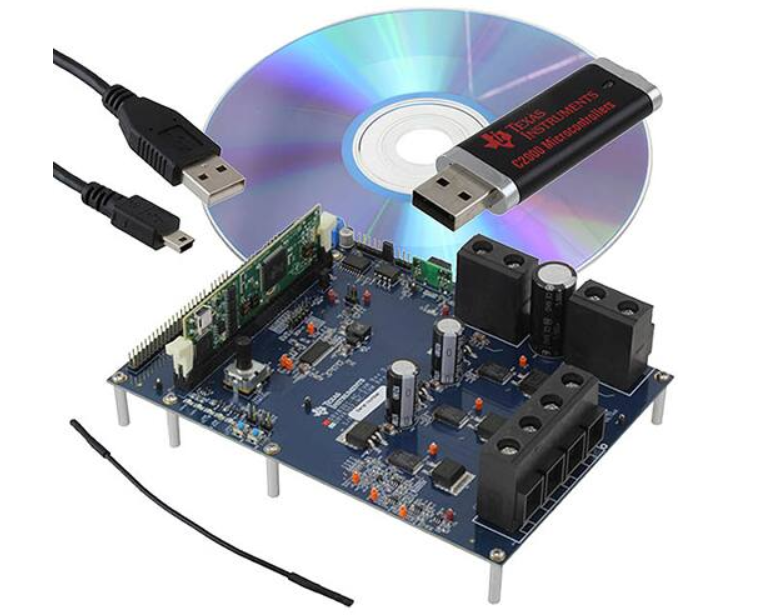
Figure 4: Designers can develop three-phase PMSM/BLDC motor drive solutions using the DRV8301-69M-KIT motor kit which includes a DRV8301 and an InstaSPIN-enabled Piccolo TMS320F28069M MCU board. (Image source: Texas Instruments)
The DRV8301-69M-KIT is an InstaSPIN-FOC and InstaSPIN-MOTION Texas Instruments technology-based motor control evaluation kit for spinning three-phase PMSM and BLDC motors. With InstaSPIN, the DRV8301-69M-KIT allows developers to quickly identify, automatically tune, and control a three-phase motor, providing an “instantly” stable and functional motor control system.
Together with InstaSPIN technology, the DRV8301-69M-KIT provides a high-performance, power-efficient, cost-effective sensorless or encoder sensor-enabled FOC platform that speeds development for quicker time to market. Applications include sub 60 volt and 40 ampere (A) synchronous motors for driving pumps, gates, lifts, and fans, as well as industrial and consumer robotics and automation.
The DRV8301-69M-KIT hardware features:
- A three-phase inverter baseboard with interface to accept DIMM100 controlCARDs
- A DRV8301 three-phase inverter integrated power module (with integrated 1.5 A buck converter) base board supporting up to 60 volts and 40 A continuous
- The TMDSCNCD28069MISO InstaSPIN-FOC and InstaSPIN-MOTION cards
- The ability to work with MotorWare supported TMDXCNCD28054MISO (sold separately) and TMDSCNCD28027F+ External Emulator (sold separately)
High-performance, high-efficiency PMSM and BLDC motor drives
The EVAL-IMM101T from Infineon Technologies is a full-featured starter kit that includes an IMM101T Smart IPM (integrated power module) that provides a fully integrated, turnkey, high-voltage motor drive solution that designers can use with high-performance, high-efficiency PMSM/BLDC motors (Figure 5). The EVAL-IMM101T also includes other necessary circuitry required for “out-of-the-box” evaluation of IMM101T Smart IPMs, such as a rectifier and EMI filter stage, as well as an isolated debugger section with USB connection to a PC.
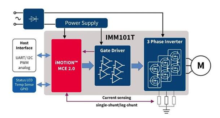
Figure 5: The IMM101T eval board is a complete solution including a motion control engine (MCE 2.0), gate driver, and 3-phase inverter capable of driving PMSM and BLDC motors using sensorless FOC. (Image source: Infineon Technologies)
The EVAL-IMM101T was developed to support designers during their first steps developing applications with an IMM101T Smart IPM. The eval board is equipped with all assembly groups for sensorless FOC. It contains a single-phase AC connector, EMI filter, rectifier and three-phase output for connecting the motor. The power stage also contains source shunt for current sensing and a voltage divider for DC link voltage measurement.
Infineon’s IMM101T offers different control configuration options for PMSM/BLDC drive systems in a compact 12 x 12 millimeter (mm) surface mount package, minimizing external component count and printed circuit board (pc board) area. The package is thermally enhanced such that it can perform well with or without a heatsink. The package features a 1.3 mm creepage distance between the high-voltage pads beneath the package to ease surface mounting and increase the robustness of the system.
The IMM100 series integrates either a 500 volt FredFET or a 650 volt CoolMOS MOSFET. Depending on the power MOSFETs employed in the package, the IMM100 series covers applications with a rated output power from 25 watts (W) to 80 W with 500 volt/600 volt maximum DC voltage. In the 600 volt versions, the Power MOS technology is rated at 650 volts, while the gate driver is rated at 600 volts, which determines the maximum allowable DC voltage of the system.
24 volt motor control eval system
Designers of 24 volt PMSM/BLDC motor drives can turn to Renesas’ RTK0EM0006S01212BJ motor control evaluation system for the RX23T microcontrollers (Figure 6). The RX23T devices are 32-bit microcontrollers suited for single inverter control with a built-in floating point unit (FPU) that enables them to be used to process complex inverter control algorithms. This helps to greatly reduce the man-hours required for software development and maintenance.
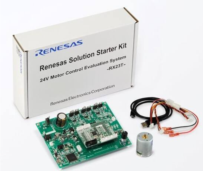
Figure 6: Renesas’ 24 volt motor control evaluation system for the RX23T microcontroller includes an inverter board to drive the PMSM that’s included in the evaluation package. (Image source: Renesas Electronics)
In addition, due to the core, the current consumed in software standby mode (with RAM retention) is only 0.45 microamperes (μA). RX23T microcontrollers operate over the range of 2.7 to 5.5 volts, and are highly compatible with the RX62T line at the pin arrangement and software level. The kit includes:
- 24 volt inverter board
- PMSM control function
- Three-shunt current detection function
- Overcurrent protection function
- CPU card for RX23T microcontroller
- USB mini B cable
- PMSM
Conclusion
BLDC and PMSMs can be used to deliver precision motion control solutions that are compact and highly efficient. The use of sensorless vector control with BLDC and PMS motors adds the advantage of eliminating the sensor hardware, thereby reducing costs and improving reliability. However, sensorless vector control in these applications can be a complex and time-consuming process.
As shown, designers can turn to development platforms and evaluation boards that come with sensorless vector control software. In addition, these development environments include all of the motor controller and power management hardware integrated into a complete system, speeding time to market.