

 radar technology in detail, particularly)
In this application note, we will look at frequency-modulated continuous waveform (FMCW) radar technology in detail, particularly the wideband 76 – 81 GHz range. We will describe how you can use Keysight’s solutions to test your designs to ensure maximum efficiency, reliability, repeatability, and most importantly, ensure that your devices work to the highest safety standards possible.
Introduction


It is reported that 1.35 million people die from road accidents every year, with thousands more injured. This is the main reason why radar specialists have been recruited by key players in the automotive industry, to develop automotive radar systems that not only improve car safety but also meet key criteria such as size and cost. Because of this market demand, various radar systems, such as adaptive cruise control (ACC), stop-and-go, blind spot detection (BSD), lane change assist (LCA), and rear crash warning (RCW), are now widely used in vehicles.
Radars based on a frequency modulated continuous waveform (FMCW) is the key technology used in most automotive radar applications today. Unlike more traditional pulsed radar, FMCW radar using continuous wave modulation can avoid a high peak-to-average power ratio (PAPR) in transmission, which simplifies the design process for antennas and RF components like power amplifiers. Consequently, an automotive radar system based on this technology offers more advantages, such as better performance with simplified RF components, small size, lightweight, and low cost.
In this application note, we will study FMCW radar technology in a little more detail, particularly the wideband 77 – 81 GHz range, and describe how Keysight’s solutions can help you test your designs to ensure maximum efficiency, reliability, repeatability and most importantly, ensure that your devices work to the highest safety standards possible. Key test parameters discussed include frequency linearity, chirp rate, phase error, power deviation and many more.
What Is FMCW and Why Use It?
FMCW is a type of radar sensor that can continuously transmit signals like a simple continuous-wave (CW) radar. However, unlike CW radar, the operating frequency of FMCW can be changed during the measurement, therefore we can say that the transmitted signal is frequency modulated. This type of radar has been around for many years, but these days the most widely used application is within the automotive radar domain.
So why is FMCW used so widely in automotive radar? Here are the advantages:
- The potential narrow resolution allows measurement of very small The minimal measurable range is comparable to the transmitted wavelength.
- Very high accuracy of range
- Unlike pulsed radar, with FMCW you can simultaneously transmit and measure the received
- Because the transmit and receive signals are “always on”, there is zero blind range. This means that there is no “blind spot” between transmit and receive, where something could be
- Pulsed radar systems have high levels of peak power; this is not the case for
- The received signal is mixed down to lower frequencies, so the processing circuitry and algorithms need not be so complicated.
- Because of the simpler circuit design, and the capabilities of modern digital signal processors (DSPs), the overall cost and the size and weight of FMCW radar modules are lower than other radar standards.

FMCW – How does it work?
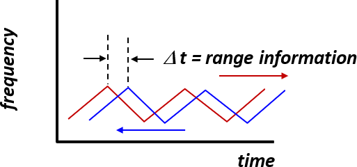
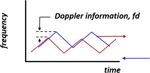
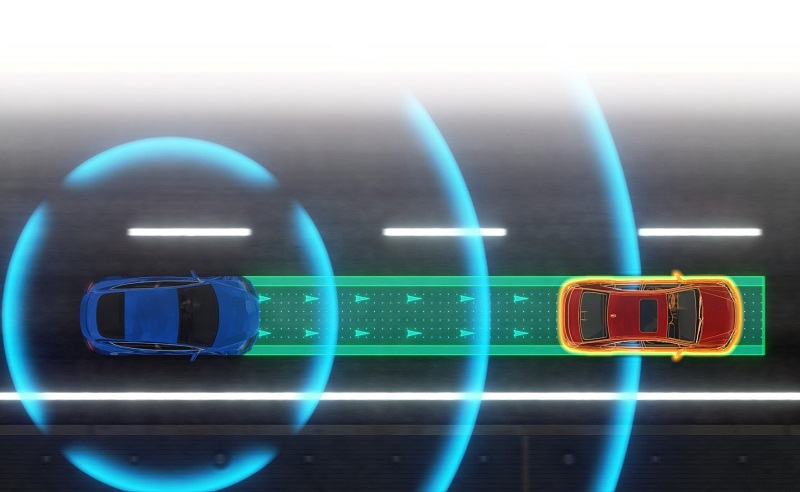
Figures 1a and 1b give a visual overview of FMCW radar detection. A shift in both time and frequency between the transmit and receive signals determine range and velocity of targets.
The received signal is a time-delayed version of the transmitted signal where the delay, Δt (delay in time), gives the range information and fd (delay in frequency) is the Doppler information. Because the signal is always sweeping through a set frequency band (for example 77 – 81 GHz), at any moment during the sweep, the frequency difference between the transmit and receive signals, f1 and f2, is constant.
Both f1 and f2 are usually called the beat frequency, and there are two measurements made, both on the rising and falling edge of the signal (also called the chirp). In the case of a single target, both the rising and falling beat frequencies are required to ensure the equations can be solved unambiguously. Because the sweep is linear, we can derive the time delay from the beat frequency, and from this also calculate the range.
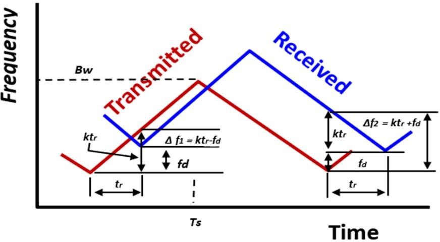
Figure 2 gives us a more in-depth overview of the different parameters required to make real measurements to calculate the range and velocity.
Δf1 = ktr – fd Δf2 = ktr + fd
k = frequency slope
tr = time delay and ktr is the frequency shift due to time delay.
To calculate the Doppler shift, fd = (2 / lc )*Vr, where Vr is the radical velocity of the object.
To calculate ktr, ktr = ((2 / C)*(Bw / Ts))*R, where C = constant, Bw is the signal bandwidth, Ts is the chirp duration and R is the range to the target
Use the beat frequency for both the rising and falling chirp to determine the velocity and range.
Δf1 = ((2 / lc )*Vr) – (((2 / C)*(Bw / Ts))*R)
Δf2 = ((2 / lc )*Vr) + (((2 / C)*(Bw / Ts))*R)
Key measurements
Here are the key questions you need to ask, to accurately characterize an FMCW radar signal.
- Is the sweep bandwidth of the signal correct? Typical automotive radar technology works in the 24 GHz, 77 GHz and 79 GHz frequency bands, and each of these can have a different sweep For example, at 24 GHz, we typically see bandwidths in the order of 100’s of MHz, where at the higher frequencies, bandwidths can be 1 GHz and greater. A traditional swept-tuned spectrum analyzer can sweep across the entire band to view the envelope of the signal.
- Why a larger bandwidth at higher frequency bands? Greater bandwidths allow finer resolution, thus allowing much better target separation capability. Using higher center frequencies also increases the Doppler resolution. Therefore, automotive radar standards are moving from 24 GHz to 77/79
- Validate the linearity of the FM sweep. Since FMCW is comprised of a frequency sweep, the linearity of that sweep is important. Any ripples or anomalies with the sweep can cause a degradation in the accuracy and resolution of the range and radial
- Measure the chirp length and chirp rate. The chirp length and rate affect the ability to determine the radial velocity. Due to possible “ghost targets”, multiple chirps are analyzed to give greater measurement
- What about signal power?
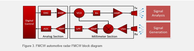
System Validation – How Does It Work?
Effective radar system design requires comprehensive system validation – a time-consuming and expensive process. Radar engineers are not only required to validate the radar transmitter performance (signal analysis) but also need to test the radar receiver performance. Radar receivers must be tested with realistic threats, sensitivity and jamming scenarios. Generating ultra-wideband (UWB) signals with Doppler frequency offsets, target echoes and clutter to perform receiver verification can be challenging. Designing and testing UWB radar systems requires a variety of signal sources, target environment setups and measurements. Carefully designed and optimized waveforms are essential to ensure excellent real-world performance.
Signal Generation
Before we show a measurement, we want to show how you can use Keysight signal generators to create an FMCW signal. This is useful if you do not have multiple devices available to test, or if you want to create a signal interference solution to allow testing of your devices in the presence of other (not necessarily FMCW) signals.
In this section, we will introduce signal generation using a Keysight M8195A arbitrary waveform generator (AWG), and then show how you can use option BHP of Keysight’s VSA (vector signal analysis) software to analyze FMCW radar signals. Option BHP is a dedicated option for FMCW signal types and allows easy setup and detection of these signals. While there are multiple configurations available for automotive radar analysis with Keysight, we will be using option 060 which includes the Keysight N9041B, 2 Hz to 110 GHz spectrum analyzer to capture the signal. This allows us to capture the signal without using any external mixing, thus maintaining the highest signal integrity.
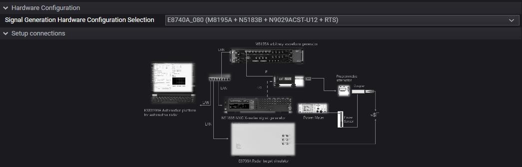
The signal generation configuration consists of the three instruments below:
- M8195A 65 GSa/s Arbitrary Waveform Generator
- N5183B MXG Microwave Analog Signal Generator, 9 kHz – 40 GHz
- N9029ACST-U12 WR12 VDI compact Upconverter
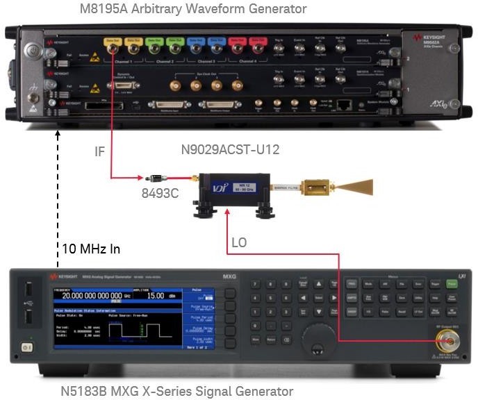
Channel 1 Data Out on the M8195A is connected to the intermediate frequency (IF) input of the N9029ACST-U12 via a 6-dB attenuator pad, while the Channel 1 Complement Data Out is terminated with a 50 Ohm load. The IF input power is recommended to be kept at < -15 dBm for linear region operation.
The local oscillator (LO) signal is provided by N5183B analog signal generator. The N9029ACST-U12 upconverter requires a LO frequency that is half of the carrier frequency Fc, thus users can select the LO frequency in the range of 30 – 45 GHz.
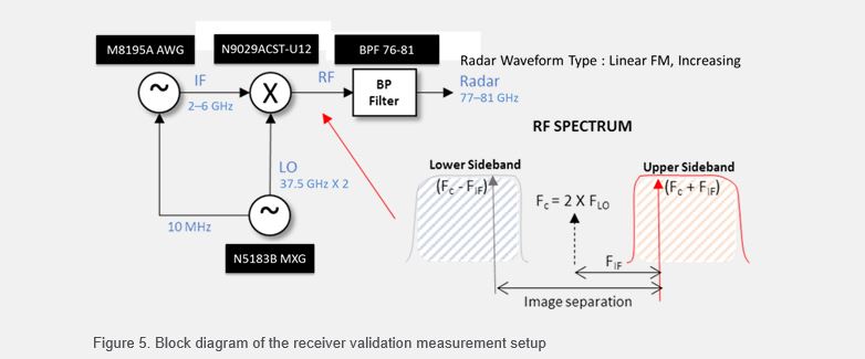
A simplified block diagram of the system is shown in the figure below. M8195A AWG provides an IF signal to be mixed with a fixed LO signal from the MXG to produce a millimeter wave signal. The up-conversion process generates a millimeter wave signal with both upper and lower sideband spectrum. The mixing product is either FC – FIF (lower sideband) or FC + FIF (upper sideband), therefore a bandpass filter is needed to remove the unwanted mixing signal. In this example, the IF signal is a linear frequency sweep from 2 GHz – 6 GHz and is mixed with the LO signal at frequency 75 GHz (37.5 GHz x 2) to produce a 77 – 81 GHz FMCW radar signal. As radar signals at the lower 24 GHz frequency range are still widely in use, the same instrumentation can be used at this lower frequency.
Automotive Radar Automation
One portion of our solution that we have not spoken about yet is the KS83200A Automation Software for Automotive Radar. This is a Keysight Pathwave Test Automation Platform (TAP) based software that can sit on a separate Windows PC or on any Windows-based instrument in your measurement setup. This is a test management suite which can be used to control all hardware and software in your setup, from hardware connections and control to connect to appropriate software such as VSA to make one-click measurements.
In addition to simpler setups, many standards bodies including the European Telecommunications Standards Institute (ETSI) are working towards conformance and compliance testing for radar devices which require specific instrument setups for each test. Because the KS83200A can control and setup multiple instruments, setting up your Keysight signal analyzer or signal generator to make measurements is made much simpler as the instrument setups for all ETSI standards 3 are built-in, so it is a one-click setup to enable compliance testing. Below you can see a list of some of the ETSI tests available. It simple takes one click to add them to your test plan, and then running the TAP software automates the instrument setup.
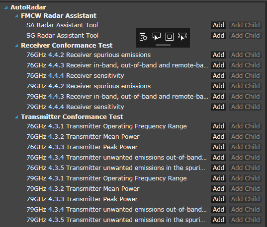
The figures below show how the KS83200A software gives a clear diagram of the hardware setup, depending on the Keysight automotive radar solution configuration. You can also see that the software is capable of controlling the generation hardware including an AWG, signal generator and radar target simulator.
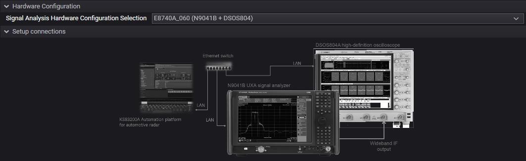

Measurement Example
For more in-depth information on how to set up this measurement, please refer to the E8740A start-up guide. As mentioned in the radar generation section, there are multiple configurations available, all of which are highlighted in great detail in the above configuration guide, but for this measurement, we will use E8740A-060 which is based on the Keysight N9041B UXA series signal analyzer plus DSOS604A oscilloscope.
The N9041B, has an internal analysis bandwidth of 1 GHz. However, as future radar modules are expected to have up to 4 GHz of bandwidth, this instrument has the capability to route this wideband IF signal external to an oscilloscope of appropriate bandwidth. The VSA software can be used to control the oscilloscope to perform the measurements.
The measurement instrumentation used in this section includes, and is grouped as part number E8740A-060:
- Keysight N9041B UXA signal analyzer
- Option-H1G, 1 GHz Analysis Bandwidth
- Option-CRW, Wideband (> 5 GHz) IF out connector
- Keysight D/MSOS804A Oscilloscope
- Option 400
- Keysight 89600 series Vector Signal Analyzer (VSA) software
- Keysight 89601200C, Basic vector signal analysis and hardware connectivity
- Keysight 89601BHPC, FMCW radar analysis option
- Keysight KS83200A Automation Software for Automotive Radar
The sample signal to be measured is a repeating FMCW modulation signal pattern consisting of multiple repeating linear FM (LFM) up-chirps. The signal comprises of a repeating pattern of LFM up-chirps deviating from -500 MHz to +500 MHz relative to the center frequency (1 GHz total deviation) over a 90 usec time interval. The power level remains on constantly, and there is no time gap between each successive LFM up-chirp occurrence.
The main software component of this solution is the powerful Keysight VSA software, used in conjunction with option BHP (FMCW radar analysis option) which contains the measurement algorithms that will be used to make measurements on the FMCW signals.
Summary and Conclusion
In this application note, we have discussed the modulation schemes and technologies currently being used within the automotive radar space. We gave an overview of the automotive radar signal generation and analysis solutions available from Keysight and a quick snapshot into the capabilities of the VSA software. Using VSA in conjunction with the Keysight N9041B UXA signal analyzer and S-series oscilloscope ensures that your device is working correctly, and also adheres to the strictest tolerances, giving multiple insights to many signal parameters that can affect the end quality of the radar device. Keysight’s patented measurement science enables the performance of all the above-mentioned instruments, whether used separately or in tandem, ensuring your time is spent measuring the parameters of your device and not the specifications of your test equipment.
We also discussed the Keysight signal generation capabilities and the flexibility an AWG gives us: wide bandwidth and multi-channel signal generation which, when used in conjunction with the analysis solution and a radar target simulator, can be used for lab-based interference testing using the AWG to create real-world signals.
Finally, we spoke about the KS83200A software which can be used to control all hardware and software in your setup, from hardware connections and control to connect to appropriate software such as VSA to make one-click measurements. In addition, many standards bodies including the European Telecommunications Standards Institute (ETSI) are working towards conformance and compliance testing for radar devices which require specific instrument setups for each test – these test setups are one-click setups allowing for less setup time and more time to test.
Courtesy: Keysight Technologies