


 and electrostatic discharge (ESD).)
Electrical noise sources within vehicles fall into two types: electromagnetic inference (EMI) and electrostatic discharge (ESD). We explain these and the basic concepts of conducted and radiated EMI noise, with relevant examples.
Radiated noise is a particularly challenging aspect of today’s wirelessly connected vehicles, with radio frequency interference (RFI) a crucial part of discovering EMI sources.


EMI exists to some degree in all types of vehicles, including older internal combustion engines and modern electric vehicles. As the electronic content of cars increases, so do the potential sources of EMI and the number of vulnerable systems. Before we investigate potential EMI sources in an EV, let’s clarify some key terminology and concepts.
EMI is any unwanted electromagnetic field that can disrupt the operation of an electronic circuit. Electromagnetic compatibility (EMC), a term tightly associated with EMI, indicates that the behavior of a circuit or system is unaffected by the presence of EMI. EMC infers immunity from EMI emissions, whereas susceptibility, another term frequently used when discussing EMI, highlights that a system’s reliability and safe operation might be prone or vulnerable to EMI.
Electrostatic discharge (ESD) is another type of EMI involving high-voltage, short-duration pulses that create fast voltage transients. These fast transients can result in high levels of emitted energy. ESD occurs irregularly compared to most EMI emissions. Crosstalk describes signals from one PCB trace or wire become coupled to another and is another type of EMI.
An essential aspect of preventing and identifying EMI is an understanding that no component is ideal, and that includes all wiring, interconnect, and the circuit’s PCB. Passive components are particularly prone to parasitic elements that can propagate EMI. A capacitor, for example, will exhibit inductance, DC resistance, and impedance in addition to its nominal capacitance.
Component leads become excellent antennas at high switching frequencies, and beyond its self-resonant frequency, a capacitor becomes more of an inductor than a capacitor. Such attributes are important design considerations; for example, even though the dominant noise source might be a clock IC driving a microcontroller pin, associated components in the signal chain might be the culprits for coupling the noise.
EMI coupling
There are principal methods by which EMI propagates from a source to a susceptible receiving system. Conducted emissions flow directly between the source and the receiver through a direct electrical connection, but noise also propagates through inductive coupling and capacitive coupling.
EMI Coupling
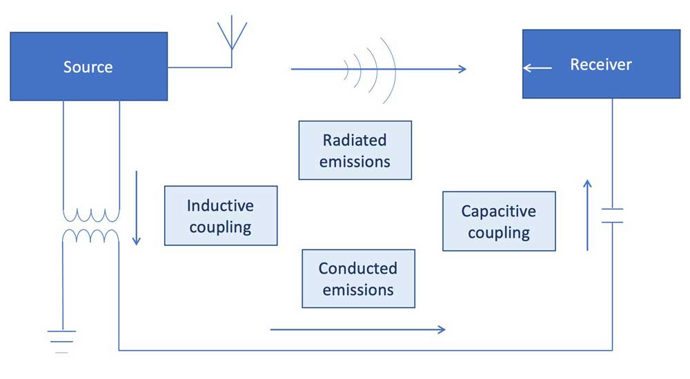
Capacitive coupling
The parasitic capacitance coupling between long PCB traces or signal wires may be sufficient to induce an unwanted noise artifact. This could be a clock signal adjacent to the output from an analog sensor. Even though the clock signal might only be between 0 – 3 VDC, the analog sensor output might be millivolts. Just a few tens of microvolts induced by the clock signal onto the analog signal will result in inaccurate, erratic and unreliable measurements, potentially disrupting system operation.
Inductive coupling
The mutual inductance between two wires can also result in artifacts from one wire transferred to the other. Circuits operating at high frequencies and with high impedance inputs are especially prone to disruption. Again, the PCB layout is an important aspect of controlling EMI. Keeping noise-sensitive analog circuit functions away from high-voltage rails, digital logic and power conversion is a specialist design skill that pays dividends.
Common impedance coupling
Multiple power supply rails will be within a complex system, such as an EV’s electronic control unit (ECU). Common impedance coupling occurs when minor noise artifacts generated by one circuit function become superimposed on its power rail. The noise can impact its operation when that power supply connection is routed to other circuit functions. Slight variations in the supply voltage to an op-amp or analog-to-digital converter will result in erroneous operation, which might be safety-critical in advanced driver assistance systems (ADAS).
Potential sources of noise in electric vehicles
Virtually any electronic-based system inside an electric vehicle can emit EMI, from infotainment touchscreens to battery management systems. However, some functional systems may create more EMI noise of higher amplitude than others. EV drivetrain electronics include high-power DC/DC converters and inverters that will generate constant high frequency switching inputs and, during acceleration, highly dynamic voltage transients.
EV showing drivetrain and batteries
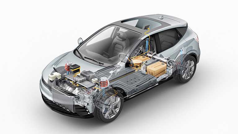
The extent of voltage transients can propagate widely through the vehicle systems, cables and interconnect, and potentially cause significant damage to sensitive electronics. Susceptible systems include advanced driver assistance systems (ADAS) functions, global navigation satellite systems (GNSS) navigation, tire pressure monitoring sensors, and collision-avoidance radar, essentially any circuit that employs analog small signal chains. Battery management systems and onboard chargers are other examples of high-power electronic circuits used in an EV. As mentioned earlier, conducted EMI from cables and interconnects attached to power electronic systems are also likely causes of erratic and unreliable behavior.
Vehicle systems also need to be immune from RFI. Infotainment systems typically integrate Bluetooth and Wi-Fi connectivity. A driver may pair a cell phone with the infotainment system to enable hands-free calls and screen mirroring of their favorite navigation app or media player. Even though the power levels of these wireless protocols are relatively low, there is still the potential to affect the operation of another wireless-based function, such as GNSS navigation or Bluetooth-connected blind spot detection mirrors. With the increasing deployment of wireless-based vehicle-to-vehicle (V2V) and vehicle-to-infrastructure (V2X) networks, ensuring vehicle systems are immune to interference from these roadside base stations is paramount.
All vehicles must comply with internationally recognized EMC legislation before being sold. Relevant standards include ISO 11451/2, CISPR 12/25, and SAE J551-x. Help from specialist EMC consultancies and test houses eases the process of pre-compliance testing through to full compliance against required standards. Anechoic chambers large enough to accommodate vehicles equipped with EMI receivers, spectrum analyzers, and ESD equipment subject a vehicle to a series of prescribed tests defined by the respective standard.