


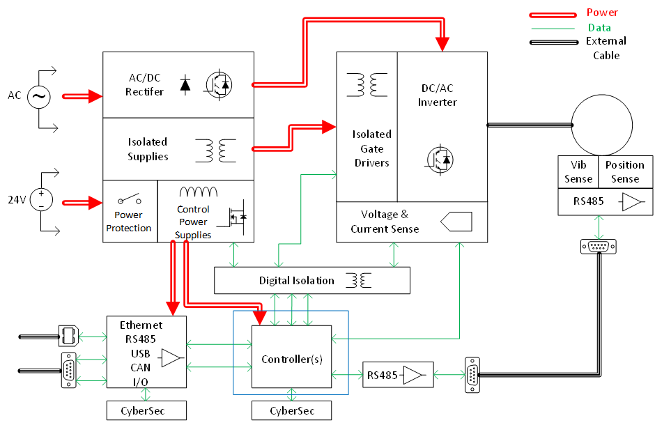
The conceptual block under consideration is highlighted once again in the architecture diagram shown above. It is clear from the diagram that the controller is truly at the heart of the system and that every other block has some form of connection to it. We will examine two main aspects related to the controller block in this blog post – namely function, and implementation. It must be underlined from the outset that while conceptually this is shown here as a single block, in reality, it often consists of more than one IC implementation. This aspect will be addressed in more detail in the implementation section.
What functions are fulfilled by the controller block?
The controller has one essential core function that impacts its design and architecture and this is the implementation of the motor drive control loops. In a sense, all other functions are subsidiary to this, and in some ways are optional, but the execution of the control loops is the single essential function of the controller. The control loops needed in a motor drive have already been introduced and these are shown again in Figure 2, with the shaded part indicating what sits inside the controller.


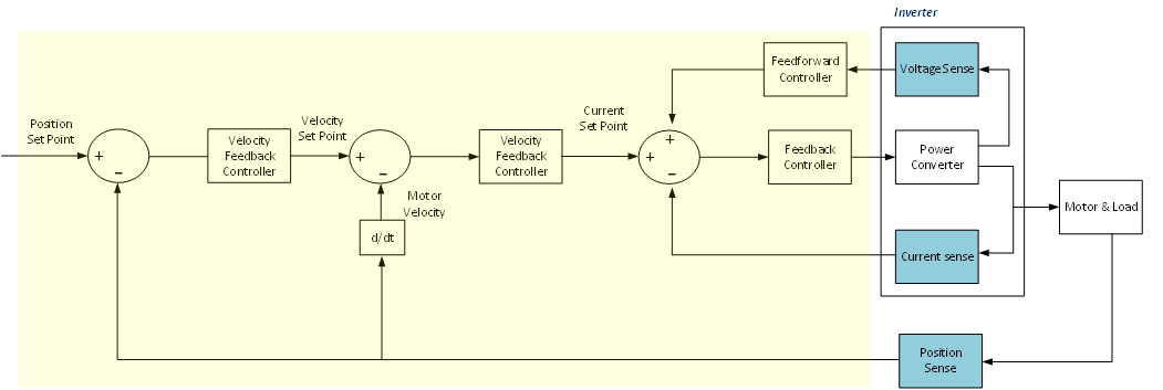
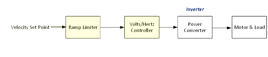
In simpler drives, not all of these blocks are implemented, and in the simplest drives, there is not even closed loop control, but typically a very simple open loop controller as shown in Figure 3, where again the portion that sits in the controller being shaded. In these very simple systems there is no or very limited feedback, and the controller can be a relatively simple device. A system like that shown in Figure 2 is assumed for the rest of the blog discussion. It is also assumed that the control loops are all implemented in a digital engine such as a micro-processor or FPGA. Analog control is not typically used any more in motor control, apart from in some very specialised applications.
One of the key requirements of the controller in implementing the drive control algorithms is that these digital control loops must be implemented in a real-time deterministic fashion. So, if the control loop update rate is for example 10kHz, then the control algorithm must be always implemented within the 10kHz time window. Control loop tasks must always take the highest priority. If the control loop task runs over, then the motor control will stop working often leading to the destruction of the motor as the power converter will not switch correctly.
Alongside the control loops (and the associated data handling from the feedback elements such as encoder, and current sensors) the controller must implement a number of other important functions:
- Communications interfaces: for example, Industrial Ethernet software stacks e.g. Ethernet I/P for communication to PLCs and other devices, USB for user interface
- User or diagnostics applications: for example, data logging, drive/motor diagnostics or drive configuration applications
- System management: startup control, monitoring faults in the drive, passing commands and references to the control loops
- Safety functions: monitoring and managing safety functions such as Safe Torque Off (STO)
- Security functions: managing secure boot, secure communication and secure firmware update, usually in conjunction with secure hardware components such as authenticators
How is the controller typically implemented?
It’s clear from this that the controller has many parallel operations to handle with the need to always ensure that the control loops are implemented in real time without being compromised by the other tasks.
- Single controller IC:
In the single controller IC approach, everything is implemented in the one microprocessor or System on Chip (SoC). This approach is becoming rarer as the complexity of motor drives increases, and as more network interfaces, user functionality, diagnostics, and safety functions are required. It is still seen widely in less complex drives, and in open-loop inverters such as shown in Figure 3. In more sophisticated drives, complex SoCs such as Xilinx Ultrascale can be used. The combination of multiple high-performance processing cores, and configurable digital blocks can enable successful partitioning of the different controller functions.
- Separate current loop controller IC:
In many drive architectures the current controller function, which includes the handling of the current feedback, as well as the pulse width modulation (PWM) functions, is handled as an individual IC, typically located on the same reference ground as the power inverter. This function has the most stringent requirements for deterministic real-time operation, so it can often make sense to have this implemented as a discrete application specific microcontroller with dedicated peripherals for motor control, or indeed as an FPGA SoC implementation (e.g. Xilinx Zynq), or as a combination of small FPGA with microcontroller. In this type of architecture, the position/velocity controller and the remaining controller functions would be implemented on a more powerful microprocessor, typically located on the safety ground side of the drive architecture.
- Separate network stack and interface IC:
Finally, the network interface functions can be separated out into a network stack processor, ASIC or FPGA implementation. This is a useful partitioning in which the complexity of the Industrial Ethernet interface can be handled separately while another processor manages user interface, safety functions and diagnostics. This allows for easier modularisation of the network interface, multiple protocols, and isolation from any network traffic issues.