


 is the workhorse of sensing applications. Measured performance values and results will also be presented to show the accuracy range in order to allow a quick evaluation for end-user applications.)
Abstract
The instrumentation amplifier (IA) is the workhorse of sensing applications. In this article, will explore some ways to take advantage of these amplifiers’ balance and excellent dc/low frequency common-mode rejection (CMR) for use with resistive transducers (for example, strain gage) when the sensor is physically separated from the amplifier. will present methods to increase the noise immunity of such gain stages while making them less sensitive to supply variation and component drift. Measured performance values and results will also be presented to show the accuracy range in order to allow a quick evaluation for end-user applications.


Detail
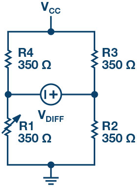
When it comes to sensors, there is little competition for what a Wheatstone bridge (Figure 1) can do. The bridge can produce a differential voltage that predictably changes in response to changes in a physical parameter with the side benefit of providing temperature and time drift immunity. The differential voltage rides atop a large common-mode (CM) voltage. To amplify the small signal from a bridge, an instrumentation amplifier is used. The beauty of an IA is that, with little or no loading of the bridge elements, it can sense the differential voltage and reject the CM to a degree that is next to impossible to achieve by a traditional op amp, due to the high degree of external resistor matching required.
The electronics involved in physical measurements are often located far from the physical parameter under measurement. For instance, a strain gage measurement, such as that buried under the tarmac at a truck weigh
station or within the structure of a bridge, is unlikely to be located next to the electronics used to read the measurement. For example, when dealing with a two-wire quarter-bridge strain gage such as Omega corporation’s SGT-1/350-TY43, placing the sensor remotely from the sensing amplifier, as shown in Figure 2, yields unsatisfactory results, even if shielded twisted pair sensor leads are used.
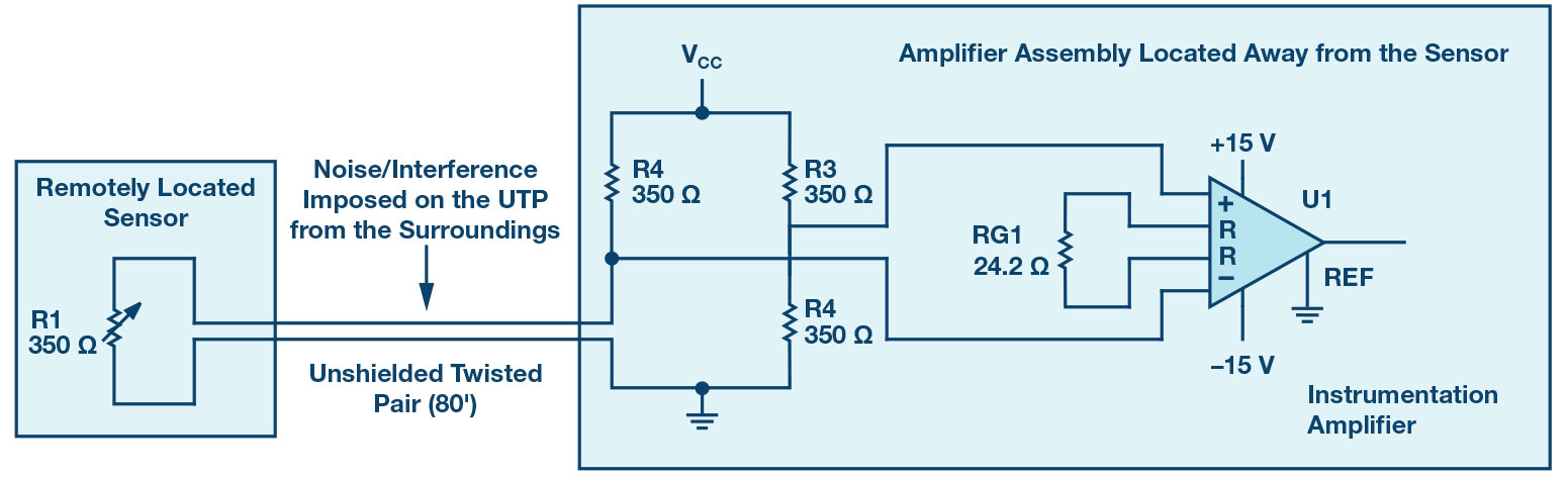
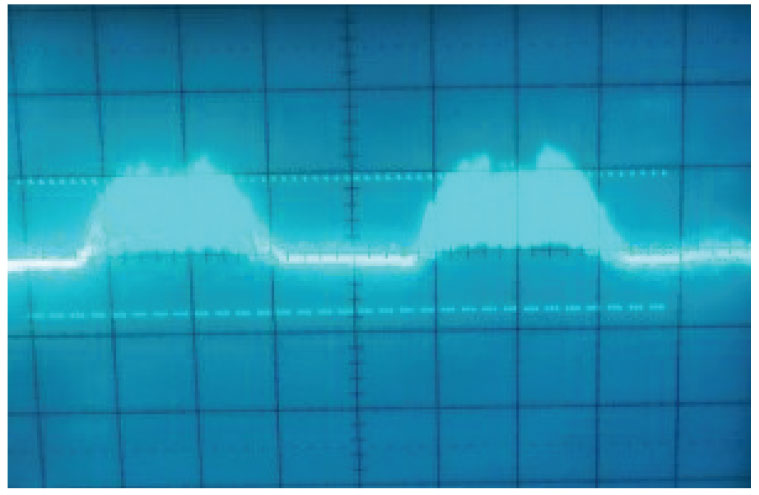
The problem is that shielded twisted pairs are not immune to all interference over long cable runs. In such a case, the well-balanced input(s) of the instrumentation cannot be relied upon to eliminate the CM pickup. The positive and negative amplifier inputs are not equally affected by the interference picked up by the long cable, and the inputs contain uncorrelated signals that CMR cannot eliminate. Therefore, it’s not a surprise to find significant noise at the output of the circuit, as shown in Figure 3, due to this unbalanced response to what seems to be CM noise.
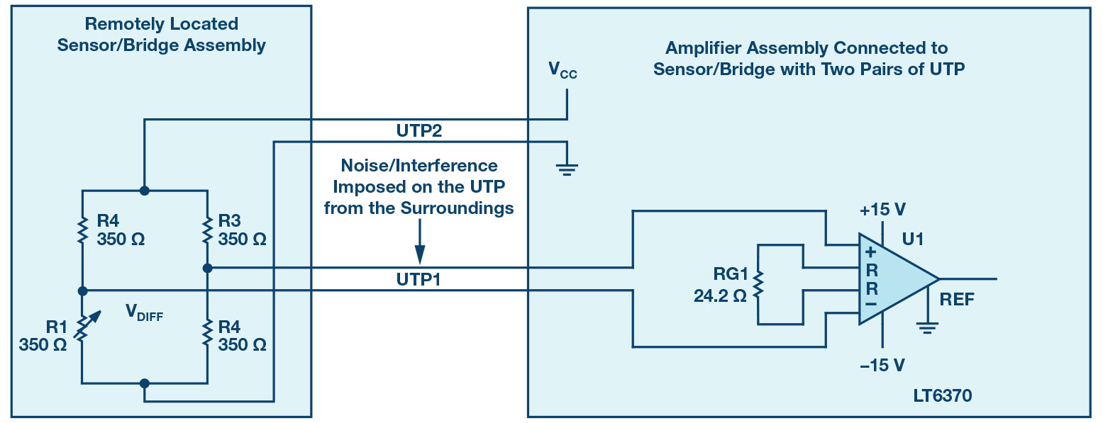
One solution for the successful extraction of the small bridge differential voltage from the CM (dc and interference) is to use two pairs of shielded or unshielded twisted pair (UTP). Done this way, both IA inputs are balanced and subjected to the same CM noise pickup. This is shown in Figure 4. A device such as the 16370, with excellent low frequency CMR (120 dB) can reliably go to work on rejecting what afflicts both IA inputs. The result is a clean output waveform at a large distance, even in noisy environments.
Having all the CMR horsepower of LT6370 at hand, one could take this idea one step further and streamline the configuration by eliminating one pair of wiring, leaving a single UTP. This concept is illustrated in Figure 5, where U2’s inputs are kept balanced for good CMR. Note how the UTP leads look identical to U2 and have identical impedance to ground (R2, R4).
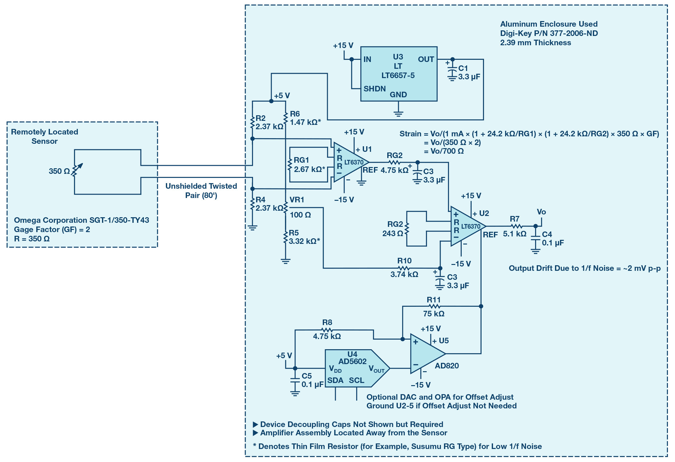
For the component values shown in Figure 5, there will be about 1 mA flowing through the sensor Reensog- With U1’s RG1 value, that stage runs at G = 10 V/V and provides a 10x replica of the voltage across Reensog at its output voltage, about 3.5 V. U1’s main task is to eliminate the interference present on the UTP long length of wire and responding only to the sensor voltage which is the sensor resistance times the ~1 mA current flowing through it. LT6370’s excellent low offset voltage and drift along with its exceptional CMR make it the obvious choice.
The other half of the Wheatstone bridge is comprised of R5, R6, and VR1 with near identical current flow as the sensor half of the bridge. Both the sensor voltage at U1 output and the reference voltage at VR1 wiper reach the differential inputs of U2 after some low-pass filtering to eliminate unwanted noise. U2 is set for high gain (G = 1 + 24.2 kKO/RG2 = 100 V/V) to magnify the very small sensor voltage on its positive input compared against the fixed, low noise reference voltage, derived from the LT6657-5 voltage reference, on its negative input. U1 output accurately represents the measured strain applied to the sensor, attached to the element or material of interest, to drive an ADC or other similar signal processing.
The optional DAC and OPA (U4, U5) tied to U2’s REF pin (which can be grounded if no offset adjust is needed) can be used to provide output offset adjustment and zeroing. By using the DAC, it is possible to shift the U2 output voltage to a desired pedestal or CM level suitable for the selected ADC. For example, an ADC with a reference voltage of 5 V can be driven directly from U2 with its zero output set to 2.5 V using the DAC driving Analog Dialogue 52-12 December 2018 U2 REF input. Done this way, 0 V to 2.5 V ADC analog input represents compression and 2.5 V to 5 V signal represents tension strain. It is import- ant to note that the device driving U2 REF pin, AD820 in this case, should maintain a low impedance to eliminate any possible gain errors.
Here is the expression for the output voltage as a function of the sensor resistance and relationship between the output voltage and the strain (€) being measured:
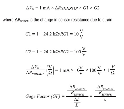
Where:
L refers to the sensor length
€ refers to the amount of strain being measured For the sensor chosen:
Reensor = 350 Q
GF= 2
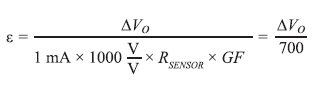
Resulting in the strain (¢):
The LT6370’s exceedingly low gain error (<0.084% at G = 10 V/V) and low input offset voltage (<50 yV max specified over temperature) guarantee that U2 is presented with a true replica of the sensor voltage, minus the interference picked up by the UTP, to compare against the reference voltage developed at U2’s inverting input. The LT6657-5 creates a stable, low noise, and low drift voltage reference, immunizing the entire circuit from supply voltage variation. Of particular importance is the LT6657-5’s low 1/f noise, which can have a significant contribution due to the large gain in the circuit.
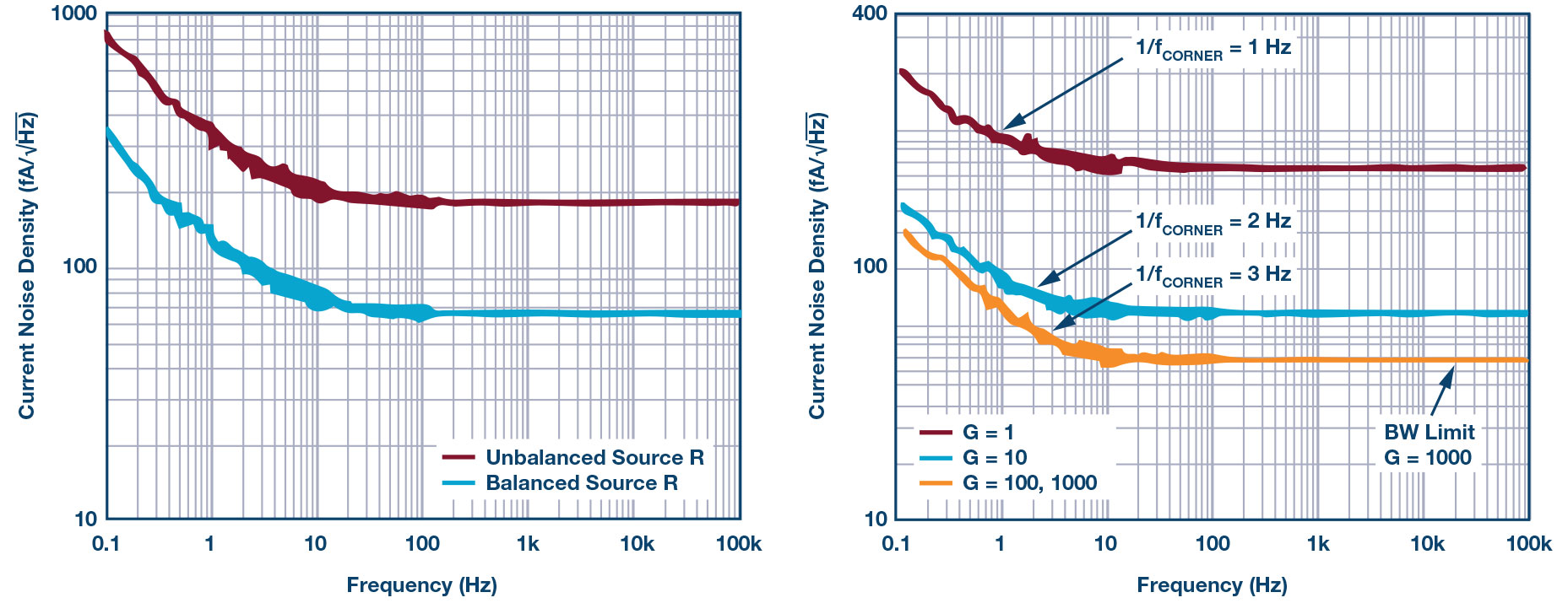
With the simple RC low-pass filters (R9, C2 and R10, C3) set to roll-off at about 10 Hz on each input of U2, the output noise can be reduced by lim- iting the bandwidth. The low (<10 Hz) LT6370 1/f noise corner frequency, as shown in Figure 6, provides an advantage by reducing the impact of the 1/f noise. Furthermore, the current noise density plot shows that it is much better to keep both input impedances balanced for the lowest current noise impact by taking advantage of the correlated component of noise at the input(s). Hence the value for R10 is reduced to 3.74 kQ in order to match the R9 impedance of 4.75 kQ due to the equivalent impedance looking into the wiper of VR1.
Summary
Placing a bridge sensor at a distance from a signal processing amplifier requires an instrumentation amplifier that can cleanly extract the measured differential voltage. The attributes of the LT6370 instrumentation amplifier enable it to process successfully signals from distant sensors via long cable runs. The LT6370 manufacturing process, which invokes on-chip heaters during production testing to guarantee over temperature drift values, further enhances the LT6370 suitability to remote monitoring applications, and improves longevity and product life in hard-to-service installations.