


Description
This reference design enables human-machine interface scenarios with an LED ring that utilizes two LP5024 LED drivers to create vivid lighting patterns. Design helps to resolve common challenges for end equipment with complicated lighting patterns and constant voltage supply. This design can also adjust LP5024 brightness with analog dimming without impacting the lighting pattern contrast ratio on dynamic ambient light sense.


Features:
- Vivid Lighting Patterns With 12-Bit, 29-kHz PWM Dimming Through and I2C Interface
- Ultra-Low Standby Current Down to 10 µA With Automatic Power Saving Mode
- Programmable Banks (R/G/B) for Easy Software Control of Each Color
- Dynamically Adjusts Brightness on Ambient Light Sense
Applications:
- Smart Speaker (With Voice Assist)
- Appliances User Interface and Connectivity Modules
- Video Doorbell
- Electronic Smart Lock
- STB and DVR
- WLAN/WIFI Access Point
- Virtual- and Augmented-Reality Headsets and Glasses
- Printers
- Video Game Console
- Home Theater-in-a-Box (HTiB)
- System Description
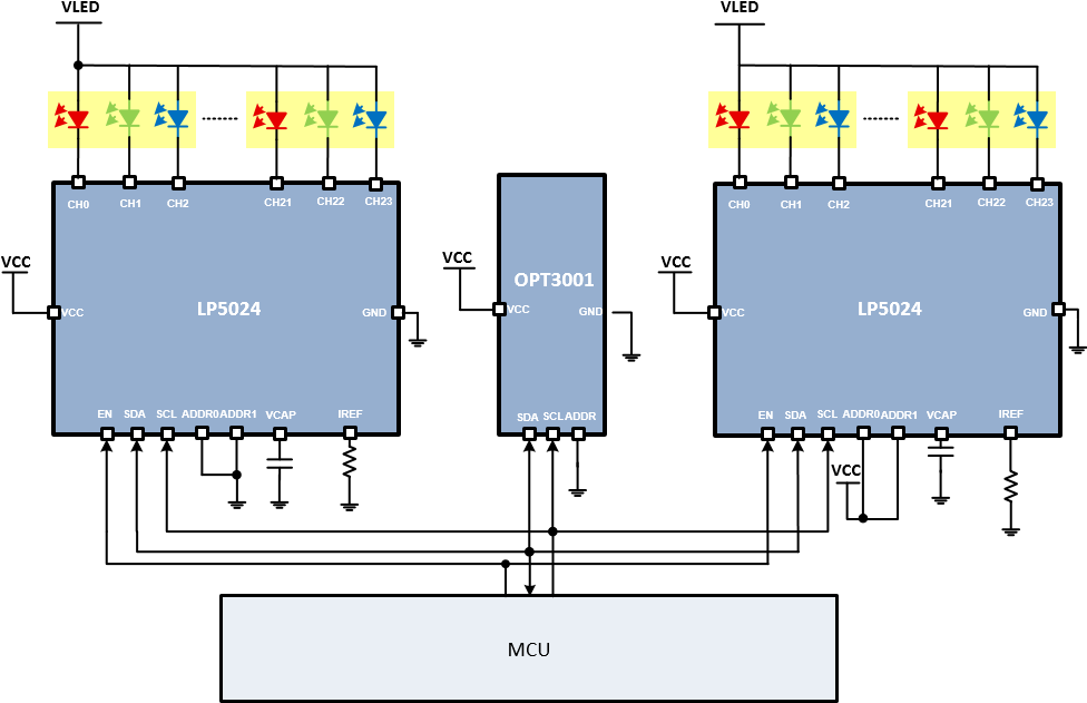
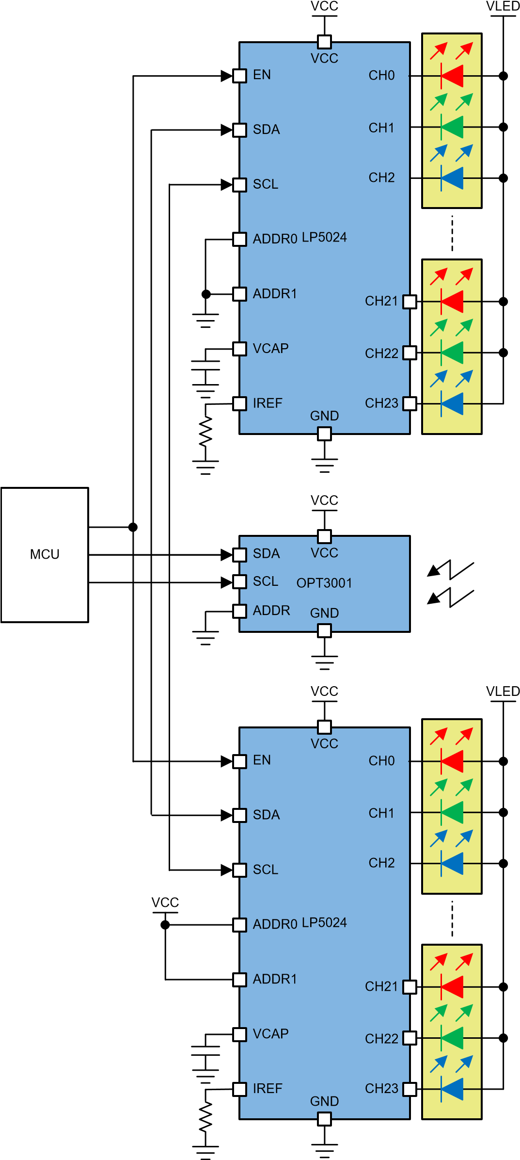
This is the design guide for the Various LED Ring Lighting Patterns Reference Design, which makes the vivid lightings pattern on the LED ring with 2 LP5024 devices. In this reference design, LP5024 linear LED drivers are used to drive 16 RGB LED modules with constant current control. OPT3001 senses the ambient light dynamically. The MSP432P401R LaunchPad sends the control signal to adjust LP5024 analog current and generate the various lighting patterns.
1.1 Key System Specifications
Table 1. Key System Specifications
| PARAMETER | SPECIFICATIONS | |
| Input voltage range | 3 V to 5.5 V | |
| Output current | 8 mA/channel maximum | |
| LED number | 16 RGB | |
| LED type | 19-337/R6 GHBHC-A01/2T | |
| Lighting pattern style | 7 | |
| Analog dimming control range | 1% to 100 % |
2. System Overview
2.1 Block Diagram
2.2 Design Considerations
In this reference design, two 24-channel, 12-bit, PWM ultralow-quiescent-current, I2C RGB LED drivers (LP5024) are used to drive a 16-RGB-LED module with constant current control and smooth dimming effect. The LP5024 devices improve the user experience in color mixing and brightness control for both live effects and coding efforts. The optimized performance for RGB LEDs makes the LP5024 an excellent fit for human-machine interaction applications. OPT3001 senses the ambient light dynamically. The MSP432P401R LaunchPad sends the control signal to adjust LP5024 analog current and generate the various lighting patterns.
Several considerations are taken into account for this particular design:
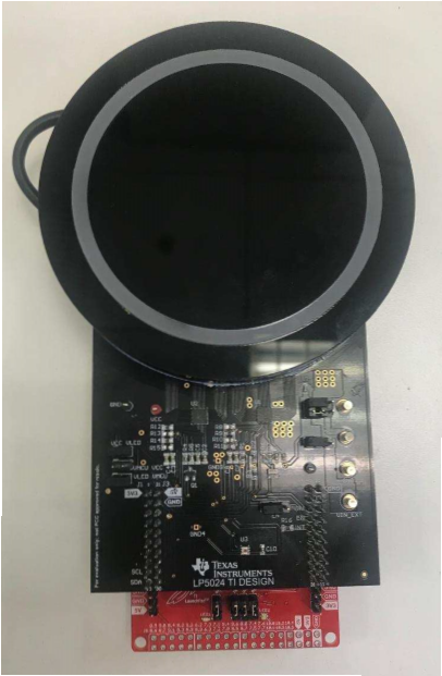
- LED map (ring) for meeting the requirement of popular human-machine interaction style.
- LED size, numbers and the diffuse design for meeting lighting pattern uniformity.
- Analog dimming in the difference ambient light lux without losing dimming resolution in lighting pattern.
These considerations apply to most human-machine interaction end equipment with day and night vision designs in some way, but the designer must decide the particular considerations to take into account for a specific design.
2.3 Highlighted Products
The following highlighted products are used in this reference design. The key features for selecting the devices for this reference design are outlined in the following subsections. For the complete details of the highlighted devices, refer to their respective product data sheets.
2.3.1 LP5024-24-CHANNEL, 12-Bit, PWM Ultralow-Quiescent-Current, 12 RGB LED Diver
The LP5024 device is an 24-channel constant current-sink LED driver. The LP5024 device improves the user experience in color mixing and brightness control, from both live effects and coding efforts. The optimized performance for RGB LEDs makes it a potential choice for human-machine-interaction applications.
The LP5024 device controls each LED output with a 12-bit PWM resolution at 29-kHz switching frequency, which helps achieve a smooth dimming effect and eliminates audible noise. The independent color mixing and brightness control registers make the software coding straightforward. When targeting fade-in, fadeout type breathing effect, the global R, G, B bank control reduces the microcontroller loading significantly. The LP5024 device also implements a PWM phase-shifting function to help reduce the input power budget when LEDs turn on simultaneously.
2.3.2 SimoleLink MSP432P401R LaunchPad Development Kit
The SimpleLink MSP‑EXP432P401R LaunchPad development kit enables one to develop high-performance applications that benefit from low-power operation. This kit features the MSP432P401R LaunchPad, which includes a 48-MHz Arm Cortex-M4F, 80-μA/MHz active power and 660-nA RTC operation, 14-bit 1- MSPS differential SAR ADC, and AES256 accelerator. All pins of the MSPEXP432P401R device are fanned out for easy access. These pins make it easy to plug in 20-pin and 40pin BoosterPack modules that add additional functionality including Bluetooth low energy, Wi-Fi wireless connectivity, and more.
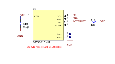
2.3.3 OPT3001 Digital Ambient Light Sensor (ALS) with High-Precision Human-Eye Response
The OPT3001 is a sensor that measures the intensity of visible light. The spectral response of the sensor tightly matches the photopic response of the human eye and includes significant infrared rejection.
The OPT3001 is a single-chip lux meter, measuring the intensity of light as visible by the human eye. The precision spectral response and strong IR rejection of the device enables the OPT3001 to accurately meter the intensity of light as seen by the human eye regardless of light source. The strong IR rejection also aids in maintaining high accuracy when industrial design calls for mounting the sensor under dark glass for aesthetics. The OPT3001 is designed for systems that create light-based experiences for humans, and an ideal preferred replacement for photodiodes, photoresistors, or other ambient light sensors with less human eye matching and IR rejection.
Measurements can be made from 0.01 lux up to 83 k lux without manually selecting full-scale ranges by using the built-in, full-scale setting feature. This capability allows light measurement over a 23-bit effective dynamic range.
2.4 System Design Theory
Two 24-channel, 12-bit, PWM ultralow-quiescent-current, I2C RGB LED drivers (LP5024) are used to drive a 16-RGB-LED module with constant current control and a smooth dimming effect. OPT3001 senses the ambient light dynamically. The MSP432P401R LaunchPad sends the PWM control signal to adjust LP5024 analog current and refresh the LP5024 device registers to generate the various lighting patterns.
2.4.1 Power Supply Design Theory
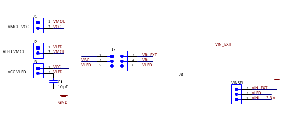
The LEDs (VLED) are powered by the external DC power directly or 3.3 V from the MSP432P401R LaunchPad through J8 ( VINSEL ).
The 3.3-V blue and green LEDs, which forward voltage can use separate power from the red LED because the red LED forward voltage is 1.8 V. The lower input voltage for the red LED reduces the power dissipation from the LED driver. J7 is the configuration jumper.
LP5024 supports 1.8-V, 3.3-V, and 5-V I2C communication logic leves, which means the difference power rail can be used in VCC, I2C interface and VLED. The device also can be configured through J1, J2, and J3.
2.4.2 LED Deign
16 RGB LED modules were placed as the LED rings for the popular human-machine interaction style. This design uses two LP5024 devices.
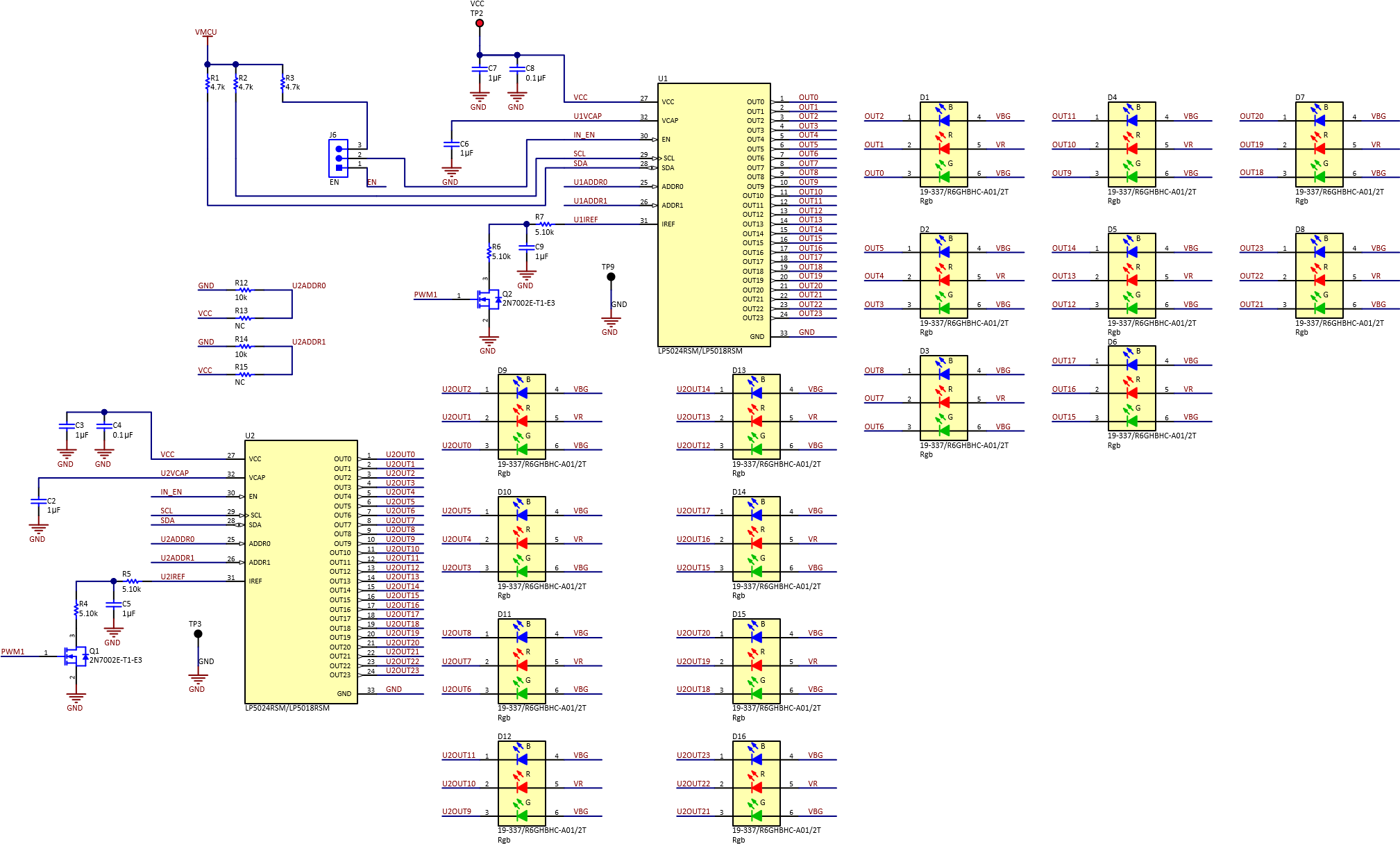
2.4.2.1 LED Current
The maximum current of each LED is 8 mA.
The constant-current value (ISET) of all 24 channels is set by a single external resistor, RIREF. The value of RIREF can be calculated by Equation 1.
VIREF
RIREF=KIREF ×
ISET
where:
- KIREF = 105
- VIREF = 0.7 V (1)
The maximum current of each LED is 8 mA.
Select R4, R5, R6, R7 with a value of 5.1 kΩ.
2.4.2.2 LP5024 Analog Dimming Circuit Design
The source current of IREF pin determines the LP5024 constant-current value (ISET). The input PWM signal filters it as DC voltage with a large capacitor. The IREF is calculated from equations based on the schematic.
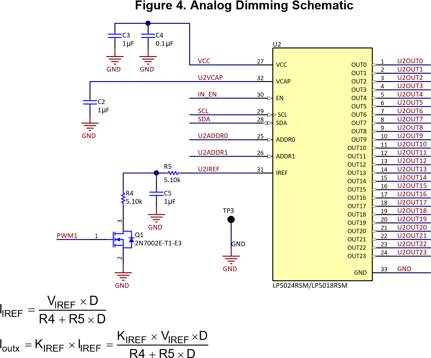
where
- K = R5 / (R4 + R5)
- D is duty cycle of the PWM Make R4 = R5, then K = 1 / 2.
Ioutx K IREF u VIREF uD
R4 u 1 D
2.4.3 OPT3001 Design
Use the OPT3001 typical application to measure ambient light lux. Make sure that the C1 capacitor is placed close to the VDD pin.
2.4.4 Relation Between Pattern Brightness and Ambient Light Lux
When lux is 0, the minium brightness is 1%. When lux is higher than 2000, the maximum brightness is 100%. When the lux is between 0 and 2000, the brightness has a linear relation with the lux.
Courtesy: www.ti.com