


 networks continue to expand at a rapid pace)
Introduction
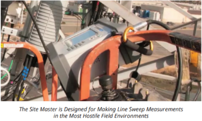
Wireless communications such as cellular and public safety Land Mobile Radio (LMR) networks continue to expand at a rapid pace. As networks become more densely packed into the available spectrum, network planning and optimization continues to increase in importance. Many operators have their own teams to install new base stations and others rely on prime contractors (often called turf vendors) who specialize in this field and are responsible for different geographic regions. In both cases, it is essential that documentation is available to confirm that the new base stations have been installed in compliance with the requirements defined by the planning departments. A key part of most new base station installations is the RF cable feeds and antenna systems. Depending on the terrain and local environment, base stations may have transmitters on the ground with long RF cable feeds going to antennas that are many meters up a tower or the base station may be a rooftop site with only short RF jumper cables between the base station and antennas.


Many new cellular base stations utilize fiber optics from the base of the tower to the remote radio head (RRH) on top of the tower followed by short RF cables from the RRH to the antennas themselves. The teams installing these systems will arrive on site with a specification for key performance metrics for the RF cable feeds and antennas. The key metrics are commonly called “Line Sweep” and “Antenna Alignment”. Installation teams have to produce documentation called “Closeout Reports” that includes measurement results for the RF cables and antennas and any fiber optics if utilized. However the fiber optics report may be generated separately from the RF cable and antenna report. The creation of the reports has typically been a time consuming task performed in an office or hotel room at the end of the day.
These reports have to be submitted to the network operator for review before the site can go live and the contract team are paid. Multiwave Sensors Inc. in partnership with Anritsu Company have developed a new application that runs on Android smartphones and tablets to provide a highly automated report generator. Results data and traces are read into the smartphone and can be sent directly to the network operator for approval while the technician is still at the site. Any errors in the measurements can be quickly identified by the operator and the technician can repeat the measurement(s) in question and resend the report for approval before leaving the site, thus reducing the number of truck rolls and naturally reducing the overall expense of the site installation or maintenance. The application interfaces to a wide range of Anritsu Site MasterTM Line Sweep testers and also the Multiwave Sensors Inc. antenna alignment tools. A single consolidated report for both sets of measurements is created, shortening the time to create the report, speeding up the site approval, and contractor payment.
RF Cable and Antenna Line Sweep Basics
When new antenna systems are installed, they need to be “swept,” a process that uses RF test instruments to verify performance of the RF cable and antenna system and to locate any potential faults within the signal path. The majority of the faults in a line feed and antenna system at a typical cell site are caused by damaged or pinched cables, corroded connectors, antennas, lightning strikes, water penetration into cables, and even bullet holes or other damage caused by vandalism. Degraded cable systems and badly positioned antennas affect overall system coverage and eventually result in dropped calls. Another benefit of sweeping these components before installation is that the measurement will reveal whether the component in question is the correct component. For example, antennas are tuned to operate at specific frequency bands, yet from the outside they may appear identical in shape and size, but the wrong antenna installed will obviously perform poorly. This also applies to filters, tower mounted amplifiers (TMA), duplexers/ diplexers, lightning arrestors, and other components. The Anritsu Site Master series instruments are field portable, handheld cable/antenna analyzers (CAA) utilizing vector error correction and are ideal for field measurements of insertion loss, return loss, and distance-to-fault (DTF). They are designed to validate system performance at time of installation and provide a trouble shooting tool for resolving failures at a later date. Sweeping the cables and antennas and preparing the line sweep reports is an essential part of the overall installation process. Towers typically have at least 6 and up to 30 or more antenna systems. Each one of these systems needs to be checked for RF faults separately as individual components and while attached in various combinations. The method for doing this is normally specified by a method of procedure (MOP). This MOP often requires 6 or 7 different sweeps per cable which is 36 to more than 180 line sweep measurements per tower.
Measurements typically required for each antenna system mounted during construction commonly include:
- Antenna Return Loss will easily identify an incorrect or defective antenna. It is typically measured before installing on the tower as well as after installation
- Cable Insertion Loss can identify incorrect cable(s) and/or excessive loss usually caused by water absorption or loose/bad connectors
- Cable DTF with a 50 ohm load on the far end which is only used for troubleshooting to locate faults within the coaxial transmission line and the various connectors/components
- Cable DTF with a “Short” on the far end is used for cable length measurement
- Antenna and Cable System Return Loss is typically a Pass/Fail test with limit specified by operator
- Antenna and Cable system DTF is often considered the “birth certificate” of the site, and is used for reference purposes when troubleshooting faults at a later date
If the antenna systems must also be swept for passive intermodulation products (PIM) even more measurements may be generated for each tower. The sheer number of measurements generated during a tower build or modification results in the need to carefully manage the reporting of a large amount of trace data.
For PIM measurements, additional trace types may also be required for each antenna system mounted during construction:
- Antenna PIM Level
- Cable PIM Level
- Cable Distance-to-PIM (DTP)
- Antenna and Cable System DTP
Antenna Alignment Basics
Simply put, if the antenna is pointing in the wrong direction the network will suffer degradation. The three parameters of antenna alignment are azimuth, tilt, and roll of the antenna:
- Azimuth is a geographic direction defined from 0 to 360 degrees with respect to true north
- Tilt is an angular measurement of the antenna in the up and down direction, sometimes referred as up tilt or down tilt
- Roll is an angular measurement of the antenna in the side-to-side direction and sometimes referred to as plumb
As networks progressed from 2G and on to 5G, where we are currently, the requirement for a more accurate azimuth has also progressed. Tilt and roll have always been able to be measured accurately with a digital level, but obtaining an accurate azimuth measurement is more difficult. That’s why carriers have mandated the use of GPS antenna alignment tools instead of the magnetic compasses. A magnetic compass azimuth can be off by tens of degrees in a tower or rooftop environment. A GPS antenna alignment tool can measure azimuth to an accuracy of less than 1° and digital level technology is also built into the tool so all three parameters are measured at the same time.
GPS Antenna Alignment Tool Basics
The tool is an integrated system containing a global positioning system (GPS), two GPS antennas, a tilt/roll sensor, and associated electronics for communication and processing. As a result of these systems, the tool outputs:
- From the GPS: Azimuth, latitude, longitude, and elevation
- From the tilt/roll sensor: Tilt and roll
- From the processing: GPS integrity
Additional information such as above ground level (AGL) can be obtained using a laser rangefinder or tape drop.
Performing Antenna Alignment
The process of wireless site design, build out, and installation of equipment has many different procedures and operations. All aspects of the build out have standards and procedures that are detailed in the MOP document. The MOP is used by employees, contractors, sub-contractors, and turf vendors to carry out the step-by-step guidelines to build the carrier’s network. One of these aspects is antenna installation. Apart from the mechanical stability, electrical, and transmission requirements (line sweep and PIM), the antenna needs to be physically aimed to the correct orientation (azimuth, tilt, and roll) as defined in the MOP. This is referred to as antenna alignment.
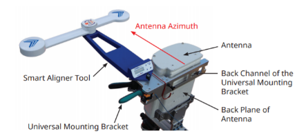
The tower crew lifts the antenna to the correct location on the tower and installs it on the mast. The tower technician attaches the universal mounting bracket to the antenna and then attaches the smart aligner tool to the bracket as shown in the image below. The back channel of the bracket and tool are both referenced to the backplane of the antenna. The backplane of the antenna defines the azimuth of the antenna.
Closeout Report Creation
Once the tool and bracket are in place, the technician powers on the tool. A smartphone installed with the Smart Aligner App (Android) and connects, wirelessly, to the alignment tool that provides a GUI for display and saving of the results. Once connected the field technician will be viewing the azimuth, tilt, and roll of the antenna in real-time. The technician can now adjust the antenna to the azimuth, tilt, and roll as specified by the MOP or the associated RF sheet for that specific antenna. Once the antenna is in the correct orientation, it is tightened, and the alignment data is verified and saved by using the Smart Aligner app. The technician can now choose to take up to 10 pictures using the Smart Aligner app. A report can then be generated that describes the antenna with respect to its orientation, location, images, and other user information. The line sweep and PIM measurements that have been saved into the Site Master memory can be consolidated into a single report with the antenna alignment results. The Anritsu product files data files (.dat, .vna, .pim) are transferred to the Smart Aligner app, saved to the site directory, and then the user can choose which files to include and creates a report.
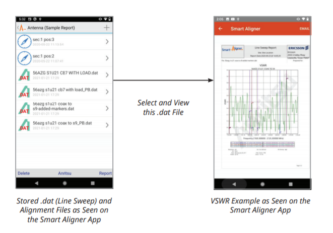
All files above (alignment, .dat, .vna, .pim) can be selected, previewed, and consolidated into a single PDF report and emailed directly from a mobile phone.
This combines the Anritsu and Multiwave Sensors reports into one PDF that can be emailed directly from the field. Consolidation of these reports is possible as a result of a partnership between Anritsu and Multiwave Sensors Inc. This report is then suitable for the final close out report of the site and can be easily emailed from the site to the head office. Below is an example of such a report using the Smart Aligner application.
Summary
For fi eld technicians who need to create close out reports quickly and reliably after installing new antenna systems in the fi eld, the new Smart Aligner smartphone application, developed by Multiwave Sensors Inc., in partnership with Anritsu Company, offers a fast and reliable solution from the market leaders in antenna alignment and line sweep instruments.