


There are two types of sensors most commonly used in various industrial automation applications: photoelectric and inductive (proximity) ones. They both have advantages and disadvantages which determine their use. For instance, an inductive sensor is capable of detecting metallic objects behind an opaque, non-metallic barrier, while a photoelectric sensor does not have such ability, because it needs to “see” an object within a certain light range. On the other hand, if we use laser light in such a sensor, its detection range can be high, even up to several dozen meters. Inductive sensors do not reach such a detection range.
A Photoelectric sensor operates by measuring the intensity of a light beam emitted by a transmitter as the light beam reaches a light-sensitive component of a receiver. Depending on the intended use of the sensor, different kinds of light are employed and the beam is modulated. Infrared light, invisible for the human eye, is used most commonly. Thanks to that, detection can be carried out without distracting attention, but the solution also has some disadvantages, which are known to anybody who ever installed a sensor meant to prevent a gate from closing when there is a vehicle standing in it. That is why laser pointers are used as additional accessories during such installation works to facilitate mutual positioning of the transmitter and receiver.


A lot of photoelectric sensors are equipped with LEDs for signalling the working status, including proper cooperation between the transmitter and receiver. Observation of the LEDs and their colours helps to mount the sensors in the right way, determine the output status or check if a response to an object is proper, which is particularly important during sensitivity adjustment.
Almost any electronic technician, automation engineer or integrator (these are specialists who use photoelectric sensors most often) will easily evaluate the criteria set by the target application and choose the right kind of a sensor. Important selection criteria include the sensor operating environment, ambient temperature, mechanical resistance (all the factors will affect the choice of the housing material, its IP rating and mounting method), the kind of light in the environment, intended use of the sensors, the required detection range, available supply voltage and output type. The sensor reaction time can be very important in some applications, although it will not be expected from wide-range sensors. The kind of detected object or objects is an extremely significant criterion. Some sensors react even when there is thin, transparent film between the transmitter and receiver, in the light beam path. Other ones require nearly full opaqueness of the object, while yet another group includes sensors equipped with a sensitivity adjustment potentiometer, which allows highly accurate setting of their triggering threshold.
It is worth paying attention to the brand when choosing a sensor. Industrial applications or devices in which the sensor has to be reliable not only for users’ safety but also for the comfort of application use should be based on proven products from renowned producers. For instance, when we get a Panasonic sensor we can assume that the sensors’ quality was checked in a solid way and so they will operate stably and reliably.
Let us see how a sensor can be used in practice, in combination with any PLC. Although the sample programme was developed for Siemens LOGO! v8, owing to the clarity of FBD language, it can be easily adapted to use on any platform.
If one photoelectric sensor is available, determination of an object motion direction can be very difficult. In order to do so, the light beam should be modulated and Doppler effect used, or the time between series of pulses sent towards the object should be measured. The methods are quite difficult for practical implementation, fairly expensive and not everybody is able to handle them. It is much easier to place the sensors one next to another and check their activation sequence.
Figure 1
Figure 1 shows the operation principle for this solution. If we use two sensors, marked e.g. as “1” and “2”, the activation of “1” and then “2” can suggest motion to the right, while if the sensors are activated in a reverse order it suggests motion to the left. Still for the algorithm to be reliable and possible to use not only for discriminating the motion direction but also e.g. for counting objects, some restrictions need to be introduced. First and foremost, quite obviously, an object must move in front of the sensors to activate them. Secondly, the maximum distance between the sensors must not be greater than the smallest dimensions of the object. This way our sensors will be activated in a sequence, e.g.:
both inactive à “1” activated à “1” and “2” activated à “2” activated à both inactive.
Thirdly, incidental motions of the object checked between the sensors should not result in an incorrect operation of the system. Not all logic errors can be eliminated because it is a programme, but it needs to be thoroughly checked with a simulator or model system, testing the algorithm in various situations which can occur in practice.
Figure 2
Figure 2 shows a sample programme in the FBD language, developed in the free LOGO! Soft Comfort environment. If we used LOGO! controller, voltage representing the logic “1” should be applied to its outputs I1 and I2. If it was LOGO! 24RC, the voltage range would amount to 18…24 V DC. If we use a version supplied with 230V AC, the logic “1” is represented by much higher voltage but then we have to pay attention to the senor output parameters and type!
As mentioned, the voltage from the contacts should be supplied to inputs I1 (from sensor “1”) and I2 (from sensor “2”). The programme is written in such a way that the motion direction from I1 to I2 results in generating an impulse at B020 gate output, while from I2 to I1 at B006 gate output.
In order to demonstrate the usability of the sample application, a bi-directional counter (B023) and a logic system (B021 – XOR gate, B022 – RS flip-flop) were connected to both gate outputs. The task of a logic system is to set the counting direction input, if positive pulses come (from gate B020) and zeroing when negative ones reach it (from gate B006), and establishing a clock-based cycle supplied to the counting input. Owing to the setting and zeroing of the counting direction input, the counter counts up (input set) or down (input zeroed).
Figure 3
The output of the Up/Down Counter unit in LOGO! is set and zeroed according to the conditions set in the counter properties window. If we enter “1” in the “On” field, as shown in Figure 3, while we leave “0” in the “Off” field, the output will be set when the counter status is higher than 0 and zeroed when it is 0. If we run the Output functional unit to the output, e.g. Q1, the output transmitter 1 of LOGO! 24RC controller will close the contacts, when the counter status exceeds 0. This way we can quickly and easily construct a device which will automatically switch on and off the light and count the persons entering and leaving a room. The light should turn on when somebody enters the room and turn off when everybody has left.
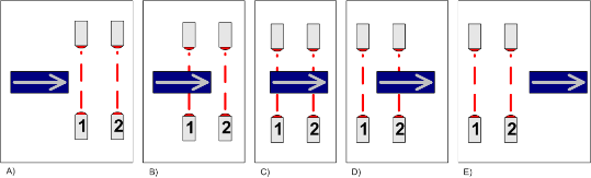
Figure 1. Principle of motion direction sensor: A) standby – the object approaches the sensors from the left, B) sensor “1” active, C) sensors “1” and “2” active, D) sensor “2” active, C) standby mode
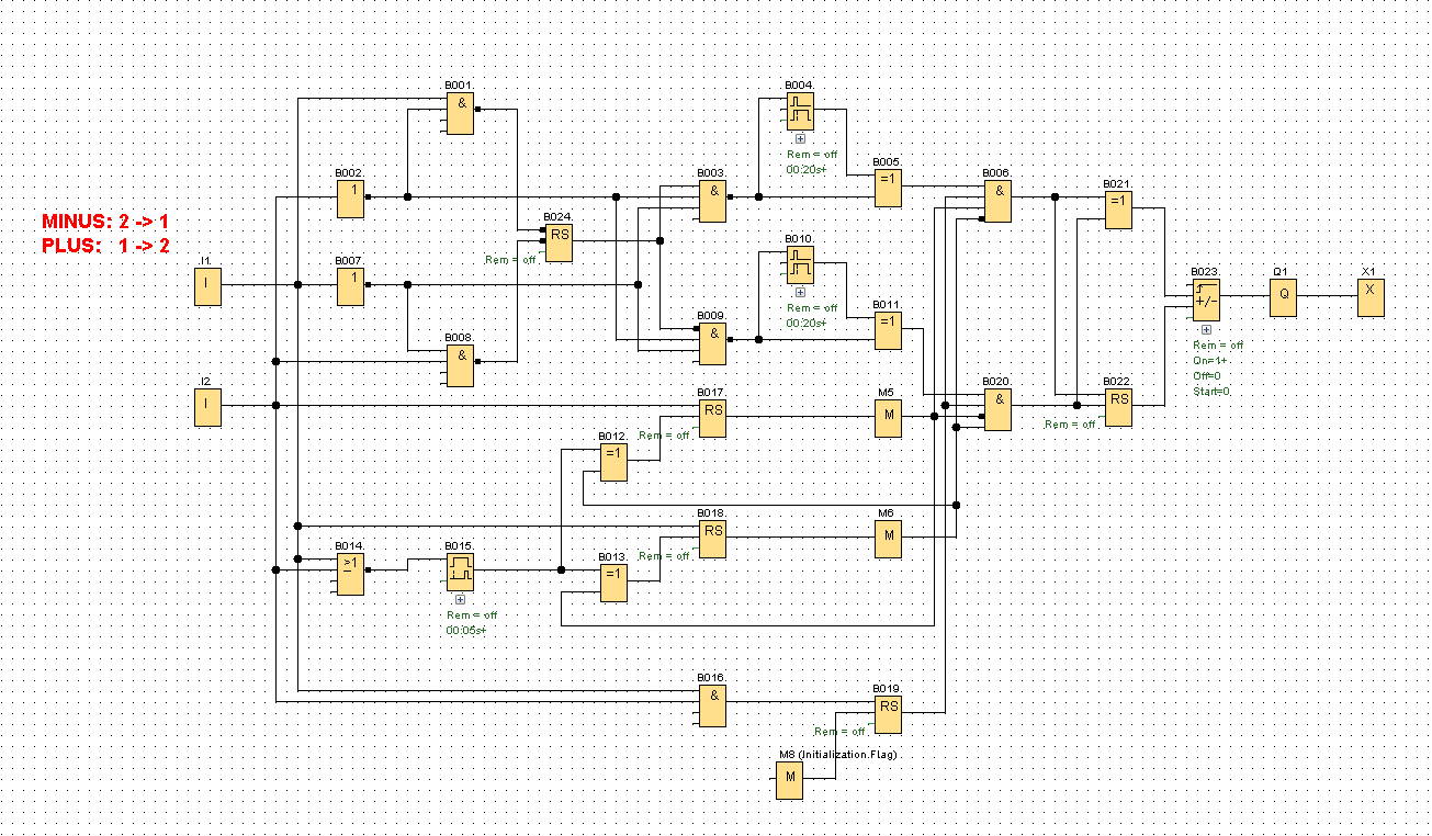
Figure 2. Sample programme in FBD language for LOGO! v8 sensor
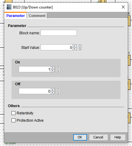
Figure 3. Up/Down Counter unit properties window