


Courtesy: Avnet
When selecting components for an EV charger design, semiconductors are the usual focus of attention. Newer power switching technologies, Silicon Carbide in particular, promise very low losses and overall cost savings. Passive components cannot be forgotten. The use of wide bandgap (WBG) switches such as SiC MOSFETs presents additional opportunities for optimization. Passive components in the power train can be smaller in size and lower in weight, which comes with reduced cost. These developments bring passive technologies into play that would otherwise be unsuitable. The main passives to consider are DC-link capacitors, filter inductors, and transformers.


The DC-link capacitor
All on- and off-board EV chargers have similar power chains. They start with a power factor correction (PFC) stage followed by an isolated DC-DC conversion stage. The output power level does not change this basic architecture, as the fastest 400kW+ roadside chargers will still typically comprise lower power modules in a stacked configuration. Each module will deliver around 30kW, to reduce stress and provide redundancy. Each stage may be bi-directional in modern designs and overall would resemble any high-power AC-DC converter.
A Typical EV charger outline with critical passive components highlighted
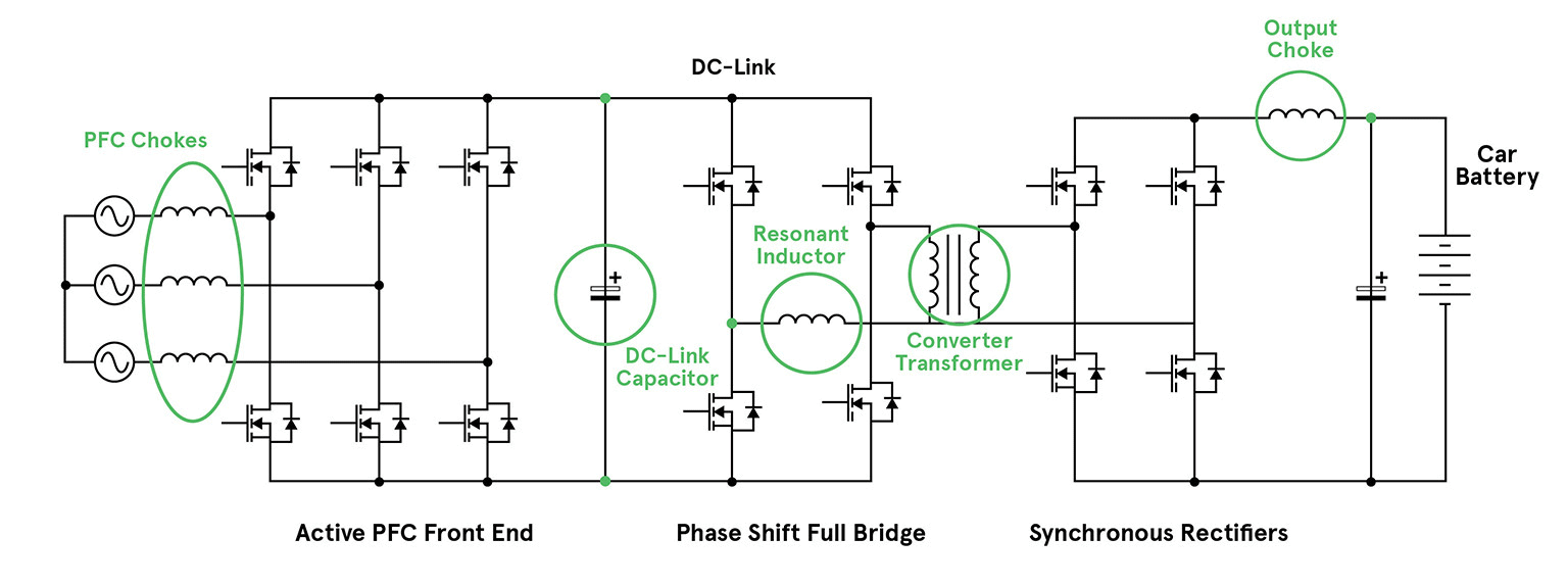
One of the main differences between a generic converter and an EV battery charger design is the sizing of the DC-link capacitor. This capacitor is positioned on the DC rail, or link, between the PFC and DC-DC conversion stages. The potential here will be a voltage of around 650V up to 1000V. In a general-purpose AC-DC converter, this capacitor is usually sized for ‘hold-up’ time, maintaining the rail for typically 18/20ms after a mains failure. At 30kW, this would need around 8,000 µF, occupying about 80 cubic inches (1300cm3). At this capacity, aluminum electrolytics are the most economically viable option.
Hold-up capacitance is calculated by equating the hold-up energy required (hold-up time x output power/efficiency), with the energy expended as the capacitor voltage drops after AC failure from its normal level to a drop-out level, perhaps from 650V to 500V. That is, 30kW x 20ms/0.90 = (0.5 x C x 6502) – (0.5 x C x 5002) giving C = 7.7 mF.
In an EV charger application, hold-up is not an issue. The size of the DC-link capacitor is based on its ability to source high-frequency ripple current for the DC-DC stage and sink ripple current from the PFC stage. The total ripple voltage and temperature rise will also be factors.
The most suitable part is determined by the Equivalent Series Resistance (ESR) and Equivalent Series Inductance (ESL) of the capacitor, as well as its capacitance. Although high capacitance for hold-up is not necessary it is still common to select AL-electrolytics. Often engineers will use large capacitors in parallel, to achieve the desired ESR and ESL. Because of the capacitors’ size, it can be difficult to keep total connection resistance low with good ripple current sharing between the components.
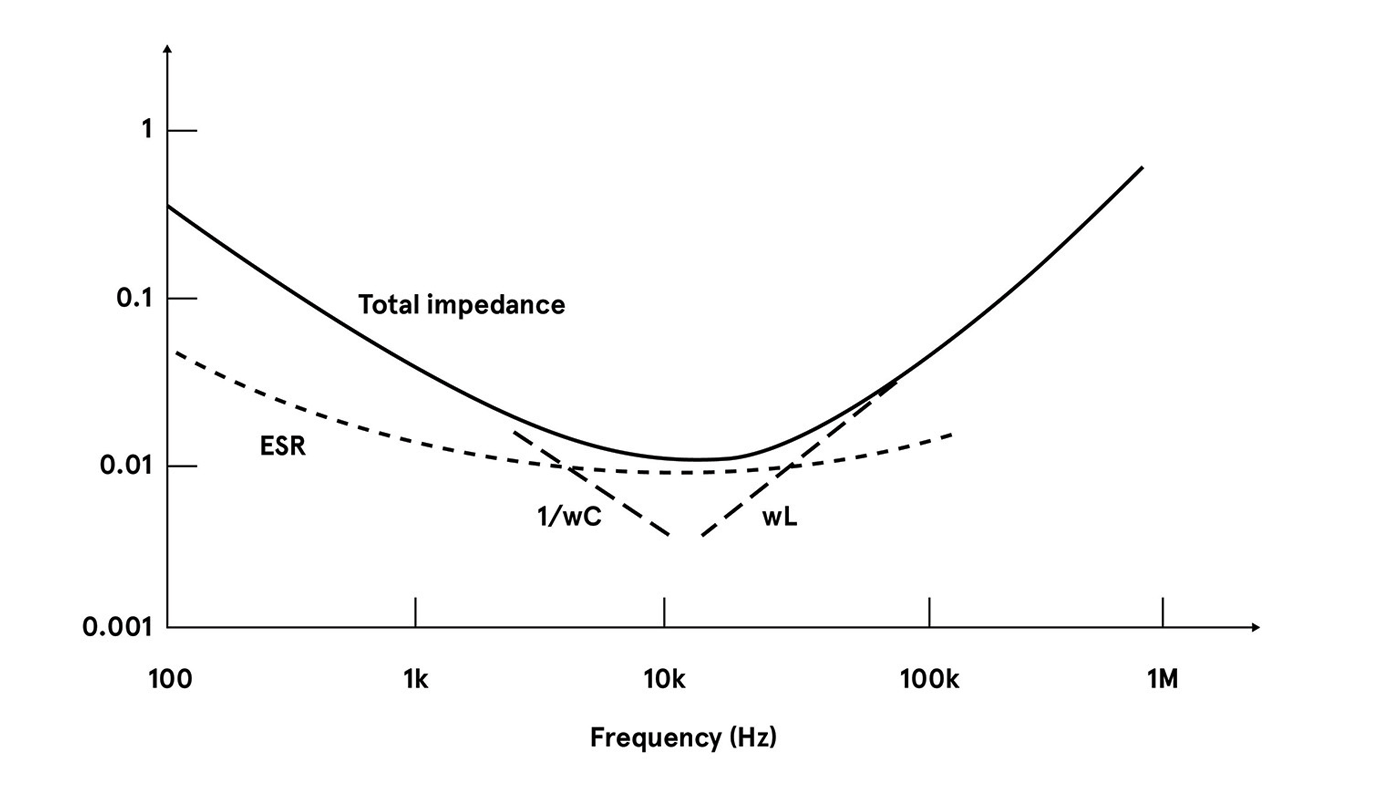
The total impedance of an AL-electrolytic will typically reach its minimum at around 10kHz. That frequency is due to the capacitance, ESL, and variation in ESR. This low frequency is not a good match when using WBG devices, which switch better at several hundred kHz. The ESR of AL-electrolytics also rises strongly at low temperatures which could be problematic at start-up, especially in a battery charger application located outside. At the other extreme, 105°C is usually the maximum rating for an AL electrolytic.
Transfer curve of an AL electrolytic
For an alternative to AL-electrolytics, look at film and multilayer ceramic capacitors (MLCCs). MLCCs have very low ESR and ESL, so the low impedance point occurs at a higher frequency. This higher frequency is more suitable when using WBG devices. The MLCC also has a longer lifetime than AL-electrolytics, perhaps 10x under the same conditions.
It is now common to see film capacitors used in the DC-link position. Film types are available rated to high voltages and operate at temperatures of at least 135°C. The common PCB-mount ‘box’ format used for MLCCs makes them easy to assemble with good packing density. They can also self-heal after over-voltage stress, unlike AL-electrolytics.
However, MLCCs are relatively high cost and low capacitance value per package. Achieving high capacitance requires using many in parallel. Some MLCCs are also relatively fragile and susceptible to substrate flexing. However, some MLCCs designed specifically for DC-link applications are now available, with fitted metal frames around paralleled parts. This eases assembly and provides some mechanical flexibility in the terminations.
Quantifying ripple current
Ripple current for a DC-link capacitor is difficult to quantify. The value depends on operating conditions, and summing the total value sunk from the PFC stage and sourced to the DC-DC stage is not simple. If the stages are not synchronized or if either stage is variable frequency, it is harder still to identify.
Simulation and bench measurements can be used, but as an approximation, for a DC link at 650V and 30kW load, the average current is about 50A allowing for inefficiencies. For a DC-DC duty cycle of 80%, this is about 25A rms sourced from the capacitor assuming a square wave. At a switching frequency of 100kHz and 10V rms ripple, only about 4µF would be needed if capacitive impedance dominates. If the capacitor ESR were 10 milliohms, this would add an extra 0.25V rms of ripple. We could guess that the ripple from the PFC stage is of the same order.
Despite these gross assumptions, it indicates that only a few tens of µF would be needed and film capacitors become practical if several are paralleled to achieve the ripple current capability. For example, four paralleled 20µF/700V metalized polypropylene capacitors can handle 62.5A rms total ripple with an overall ESR of less than one milliohm, giving less than 4 W total dissipation at 50A rms ripple current. The overall volume is 8.5 cubic inches (139 cm3).
An AL-electrolytic solution, for similar ripple current capability could be assembled from 10x 2700µF/400V parts, in a 5-parallel 2-series arrangement, with about 85A ripple current rating (10kHz) and an ESR of about 8 milliohms total. At 50A rms ripple current, this would give about 20W of dissipation overall.
Ripple voltage is much lower than the film capacitor solution, because of lower capacitive impedance, but the overall volume would be 125 cubic inches (2060 cm3) or nearly 15x larger. Further advantages of film capacitors include a particularly low ESL of a few tens of nH, adding only a volt or so to the ripple voltage waveform.
Comparing a typical MLCC solution, three in parallel could achieve 50A rms ripple rating and adequate capacitance for less than 10V rms ripple. ESR would be around 2 milliohms total and dissipation around 3W overall. Low ESR and ESL are maintained up to a frequency of at least 1MHz. This makes MLCC a good candidate for ultra-fast switching where capacitance value is less important. ESR and capacitance do vary however quite strongly with temperature and bias voltage. Typically, three modules would occupy just 0.8 cubic inches (13.25 cm3).
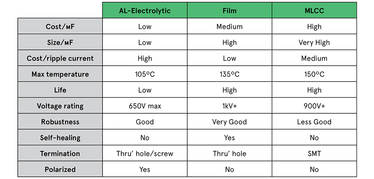
Indicative volume pricing shows four of the film parts would cost around one quarter the price of ten AL-electrolytics, while three MLCC modules would be about half the price of the ten AL-electrolytics. In practice, derating will be applied to capacitors of any type, requiring further parallel parts. That may apply more so for the electrolytics. In this case, the difference becomes even more striking. The table shows the difference in headline performance of film, MLCC, and AL-electrolytic capacitors.
Comparing capacitors for EV chargers
Magnetics in EV chargers
Magnetic components in EV chargers are like any found in AC-DC converters, but the fast charger environment and the trend toward WBG semiconductors influences the choice of fabrication technique. The main components to consider are the input EMI filter, PFC inductor, DC-DC transformer, output choke, and any additional resonant inductors, depending on the converter topology being used.
The EMI filter will comprise at least one common-mode choke in the AC input lines with windings phased so that flux from line currents cancel. This allows high inductance to be used without risk of saturation. High permeability ferrite cores are normally used but nano-crystalline material is sometimes seen for maximum inductance.
Windings are spaced to achieve voltage isolation and ideally in just a single layer, to keep self-capacitance low and self-resonance high. Differential-mode chokes are also usually necessary, and these see flux from the full line current. To avoid saturation, they are typically low inductance, wound on iron power core toroids. Some common-mode choke designs add separation to their windings to deliberately introduce leakage flux, which acts as an integrated differential mode choke. Both common-mode and differential-mode chokes are wound with magnet wire on bobbins or headers for PCB mounting.
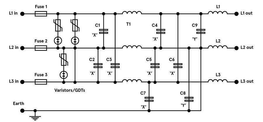
Magnetic component selection in EV chargers
The PFC choke operates at high frequency and its inductance value is chosen to match the operating mode of the stage; continuous, discontinuous, or ‘boundary’. These modes trade off semiconductor stress with potential EMI and choke size, and with the high peak currents present, a low effective core permeability is needed to avoid saturation.
A powder core would produce excessive core losses, so the preference is a gapped ferrite. This should offer minimum loss at the working flux density and frequency, and at the expected operating temperature. The component could be of bobbin construction, but a planar approach can be practical with PCB traces used as windings, giving low losses and a large surface area to help dissipate heat.
The DC-DC converter topology will invariably be a version of a forward converter, typically a full-bridge, and often a resonant type at the power levels involved. Planar transformer designs are popular as they are consistent and easy to integrate with the power switches operating at high frequency. However, safety isolation is required and the appropriate creepage and clearance distances can be difficult to achieve with this construction.
In most cases, high primary inductance is needed, achieved with an ungapped high-permeability core, and, like the PFC choke, the material is chosen for the lowest core losses. Resonant converters use an extra inductor that can be formed from the leakage inductance of the main transformer. This can be difficult to control and can limit overall performance, so normally the inductor is a separate component. The value can be very low so it could conceivably be air-cored but is more likely to utilize a core to constrain the magnetic field and reduce interactions.
An output choke, if necessary for the topology, is chosen in a similar way to the PFC choke. A desired ripple current is specified, which sets inductance for a given output voltage, duty cycle, and frequency. The DC output current flows through the choke, so a gapped ferrite is the normal core solution. The component again could be a planar construction in modern designs.
Conclusion
Passive components can become a limit to the performance achieved in EV charger designs. There are choices of components however which can leverage the characteristics of the latest semiconductor technologies to minimize losses and contribute to overall reduction in size, weight, and cost.
As a global leader in IP&E solutions, Avnet has a robust supplier line card in all regions as well as extensive design support and demand creation services. Our dedicated IP&E experts can help with everything from supply chain needs to service organization requirements.