

A market-wide trend in industrial motor drives is an increasing demand for higher efficiency coupled with increased reliability and robustness. Power semiconductor device manufacturers are continually pushing the boundaries of conduction loss and switching time improvements. Some of the trade-offs in enhancing insulated gate bipolar transistor (IGBT) conduction loss are increased short-circuit current levels, smaller die size, and reduced thermal capacity and short-circuit withstand time. This accentuates the importance of the gate driver circuit and its over-current detection and protection features. This article will discuss the issues involved in successful and reliable short-circuit protection in modern industrial motor drives, with experimental examples from an isolated gate driver in a 3-phase motor control application.
Short-circuits in Industrial Environments Industrial motor drives can operate in a relatively harsh environment in which high temperature, ac line transients, mechanical overload, miswiring, and other contingencies can occur. Some of these events can result in large overcurrent levels flowing in the motor drive power circuits.


Three typical short-circuit events are illustrated in Figure 1.
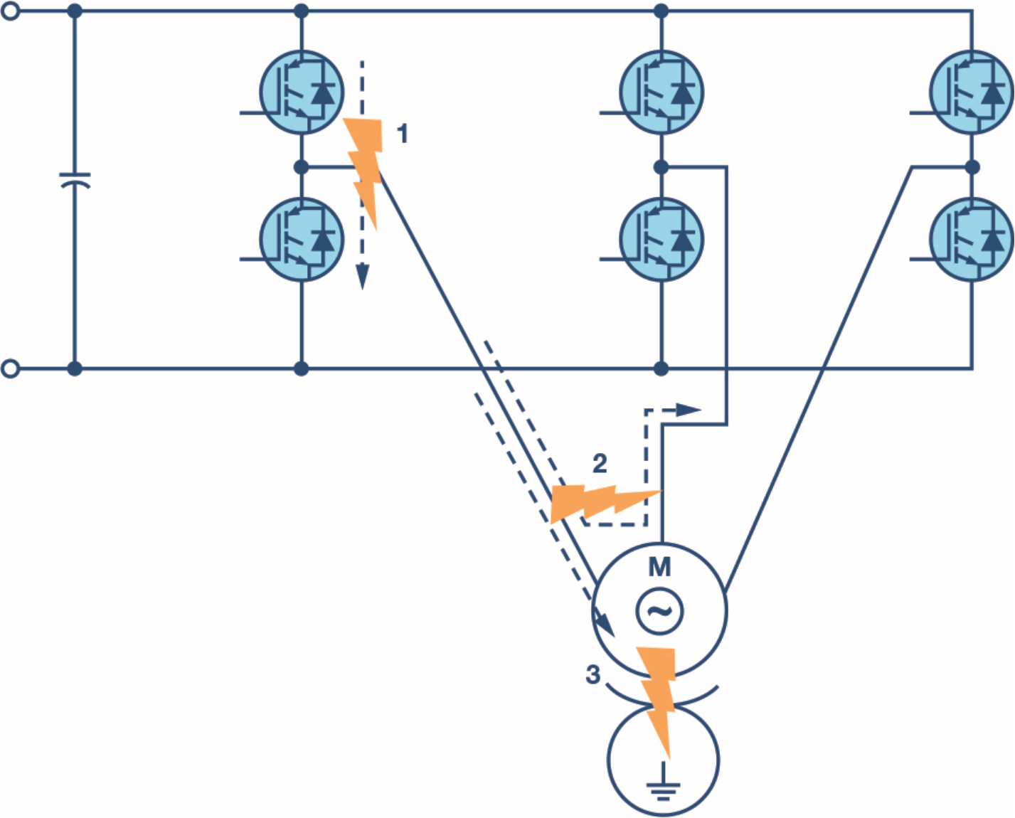
These are described below:
- Inverter shoot-through. This can be caused by the incorrect turn-on of both IGBTs in one of the inverter legs, which in turn can result from electromagnetic interference or a malfunction in the controller. It could also be caused by wear out/failure of one of the IGBTs in the leg while the healthy IGBT keeps switching.
- Phase-to-phase short-circuit. This can be caused by insulation breakdown in the motor between windings due to degradation, over temperature, or overvoltage events.
- Phase-to-earth short-circuit. This can be caused by insulation breakdown between a motor winding and the motor casing; again usually due to degradation, over-temperature, or overvoltage events.
IGBT Short-Circuit Capability
The short-circuit withstand time of an IGBT is related to its transconductance or gain and the thermal capacity of the IGBT die. Higher gain leads to higher short-circuit current levels within the IGBT, so clearly lower gain IGBTs will have lower short-circuit levels. However, higher gain also results in lower on-state conduction losses, and so a trade-off must be made. Advances in IGBT technology are resulting in the trend of increased short-circuit current levels and consequently reduced short-circuit withstand times. In addition, the improvements in technology allow for the use of smaller die, reducing module size but lowering thermal capacity, which further reduces the withstand time. There is also a strong dependency on the IGBT collector-emitter voltage, so the parallel trend toward higher dc bus voltage levels in industrial drives results in further reduction in short-circuit withstand times.
IGBT Overcurrent Protection
IGBT protection from overcurrent conditions is a critical part of system reliability, both in terms of asset destruction and indeed safety. IGBTs are not regarded as a fail-safe component and their failure can result in a dc bus capacitor explosion and complete drive failure.5 Overcurrent protection is typically implemented by means of current measurement or desaturation detection. These techniques are illustrated in Figure 2. For current measurement, measurement devices such as shunt resistors are required in both the inverter leg and phase output to cover shoot through faults and motor winding faults. Fast acting trip circuitry in the controller and/or gate drivers must then shut down the IGBTs in a timely manner in order to prevent the short-circuit withstand time from being exceeded. The main disadvantage of this method is the requirement to include two measurement devices in each inverter leg, along with any associated signal conditioning and isolation circuitry. This can be alleviated by only adding shunt resistors in the positive and negative dc bus lines. However, in many cases, either a leg shunt resistor or a phase shunt resistor will be present in the drive architecture for the purposes of the current control loop and motor overcurrent protection, and these can also be potentially utilized for IGBT overcurrent protection—provided that the response time of the signal conditioning is fast enough to protect the IGBT within the required short-circuit withstand time.
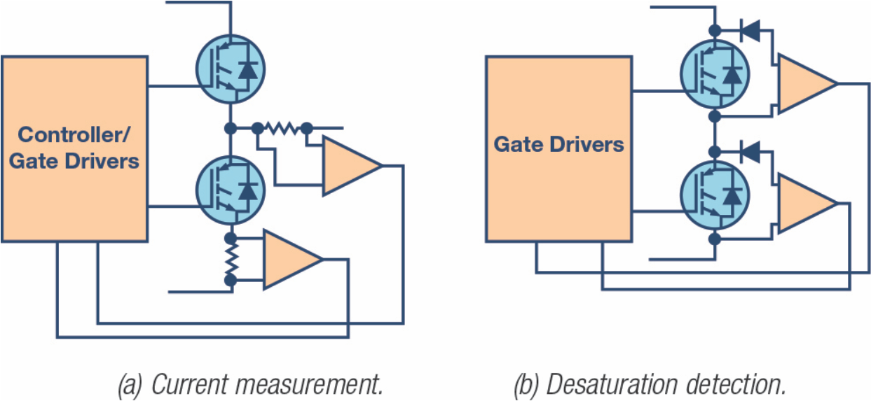
Desaturation detection utilizes the IGBT itself as the current measurement component. The diodes shown in the schematic ensure that the IGBT collector-emitter voltage is only monitored by the detection circuit during the on-time, when in normal operation the collector-emitter voltage is very low (1 V to 4 V typically). However if a short-circuit event occurs, the IGBT collector current increases to a level that drives the IGBT out of the saturated region and into the linear region of operation. This results in a rapid increase in the collector-emitter voltage. The above normal voltage level can be used to indicate the existence of a short-circuit, and threshold levels for desaturation trip are typically in the 7 V to 9 V region.
A blanking time is generally inserted between the beginning of the turn-on signal and the point at which desaturation detection is activated in order to avoid false detection. A current source charged capacitor or an RC filter is also usually added to introduce a short time constant into the detection mechanism in order to filter spurious trips introduced by noise pickup. The selection of these filter components are a trade-off between providing noise immunity and acting within the IGBT short-circuit withstand time. Having detected the IGBT overcurrent, a further challenge is faced in turning off an IGBT at abnormally high current levels. Under normal operating conditions, the gate driver is designed to turn off the IGBT as rapidly as possible in order to minimize switching losses. This is achieved by means of low driver impedance and small gate drive resistance. If the same gate turn-off rate is applied for overcurrent conditions, the di/dt in the collector-emitter will be significantly larger due to the higher current change in a short time period. Parasitic inductance within the collector emitter circuit due to wire bond and PCB trace stray inductance can result in large overvoltage levels being reached transiently across the IGBT (as VLSTRAY = LSTRAY × di/dt). Thus, it is important to provide a higher impedance turn-off path when shutting the IGBT off during a desaturation event in order to reduce the di/dt and any potentially destructive overvoltage levels.
Apart from short circuits occurring as the result of faults within the system, momentary inverter shoot-through can also occur in normal operation. In normal operating conditions, IGBT turn-on requires that the IGBT be driven into the saturation region where the conduction losses will be minimized. This typically implies gate-emitter voltages of >12 V during the on state. IGBT turn-off requires that the IGBT be driven to the cutoff region of operation so that it can successfully block the reverse high voltage across it once the high-side IGBT has turned on. In principle this can be achieved by reducing the IGBT gate-emitter voltage to 0 V. However, a secondary effect must be taken into account when the transistor on the low-side of the inverter leg is turning on. The rapid transition of the switch node voltage on turn-on causes a capacitive induced current to flow in the low-side IGBT parasitic Miller gate collector capacitance (CGC in Figure 3). This current flows through the turn-off impedance of the low-side gate driver (ZDRIVER in Figure 3), creating a transient voltage increase at the low-side IGBT gate-emitter terminals, as shown. If this voltage rises above the IGBT threshold voltage, VTH, it can cause a brief turn-on of the low-side IGBT, resulting in a momentary inverter leg shoot-through since both IGBTs are turned on for a brief period. This will not generally result in IGBT destruction, but it does increase power dissipation and compromises reliability.
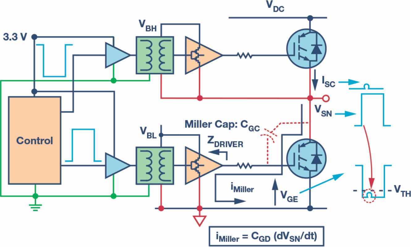
There are generally two approaches to addressing the induced turn-on of inverter IGBTs—using bipolar supplies and/or the addition of a Miller clamp. The ability to accept a bipolar power supply on the isolated side of the gate driver provides additional headroom for the induced voltage transient. For instance, a negative supply rail of –7.5 V means that an induced voltage transient of >8.5 V will typically be needed to induce a spurious turn-on. This is generally sufficient to prevent a spurious turn-on. A complementary approach is to reduce the turn-off impedance of the gate driver circuit for a period of time after the turn-off transition has been completed. This is known as a Miller clamp circuit. The capacitive current now flows in a lower impedance circuit, consequently reducing the magnitude of the voltage transient.
Experimental Example
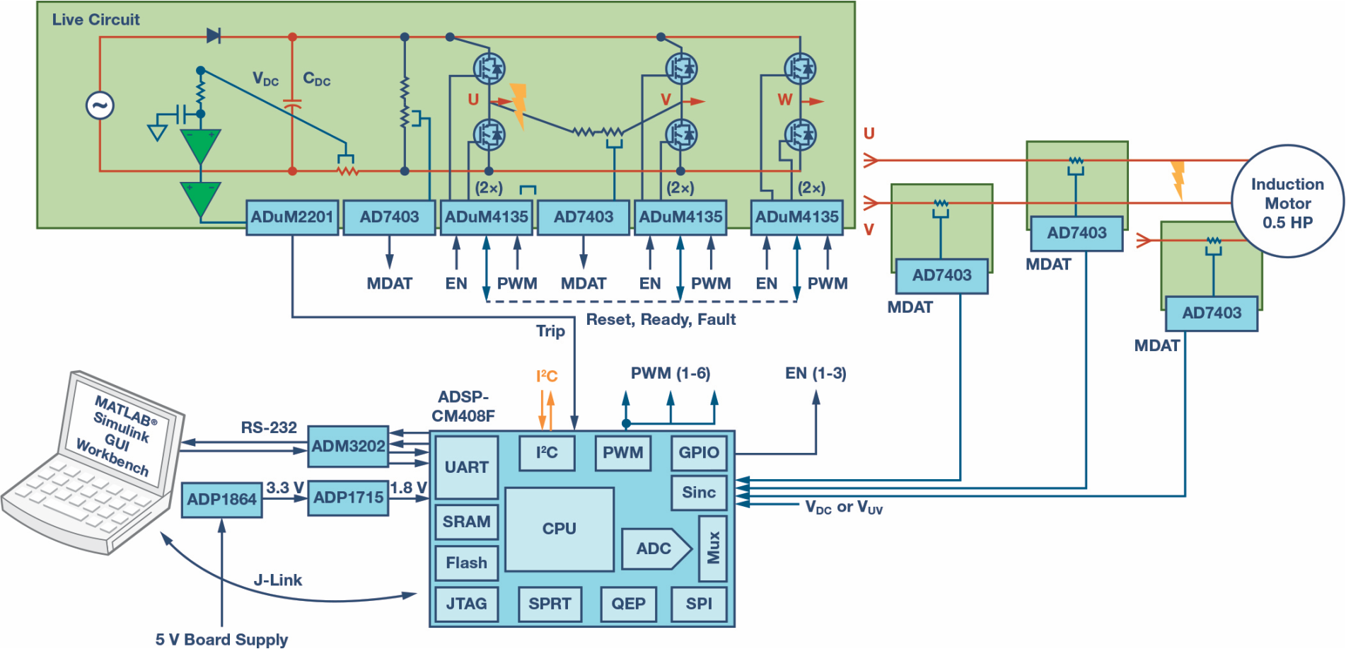
The experimental setup utilizes a 3-phase inverter powered from the ac mains through a half wave rectifier. In this case this results in a dc bus voltage at 320 V, although the system can be also used up to dc bus voltage levels of 800 V. A 0.5 HP induction motor is driven under open loop V/Hz control in normal operation. The IGBTs are 1200 V, 30 A IRG7PH46UDPBF from International Rectifier. The controller is an ADSPCM408F Cortex-M4F mixed signal processor from Analog Devices (ADI). Phase current measurement is carried out using isolated Σ-Δ AD7403 modulators and isolated gate drive is implemented using the ADuM4135, a magnetically isolated gate driver with integrated desaturation detection, a Miller clamp, and other IGBT protection features.
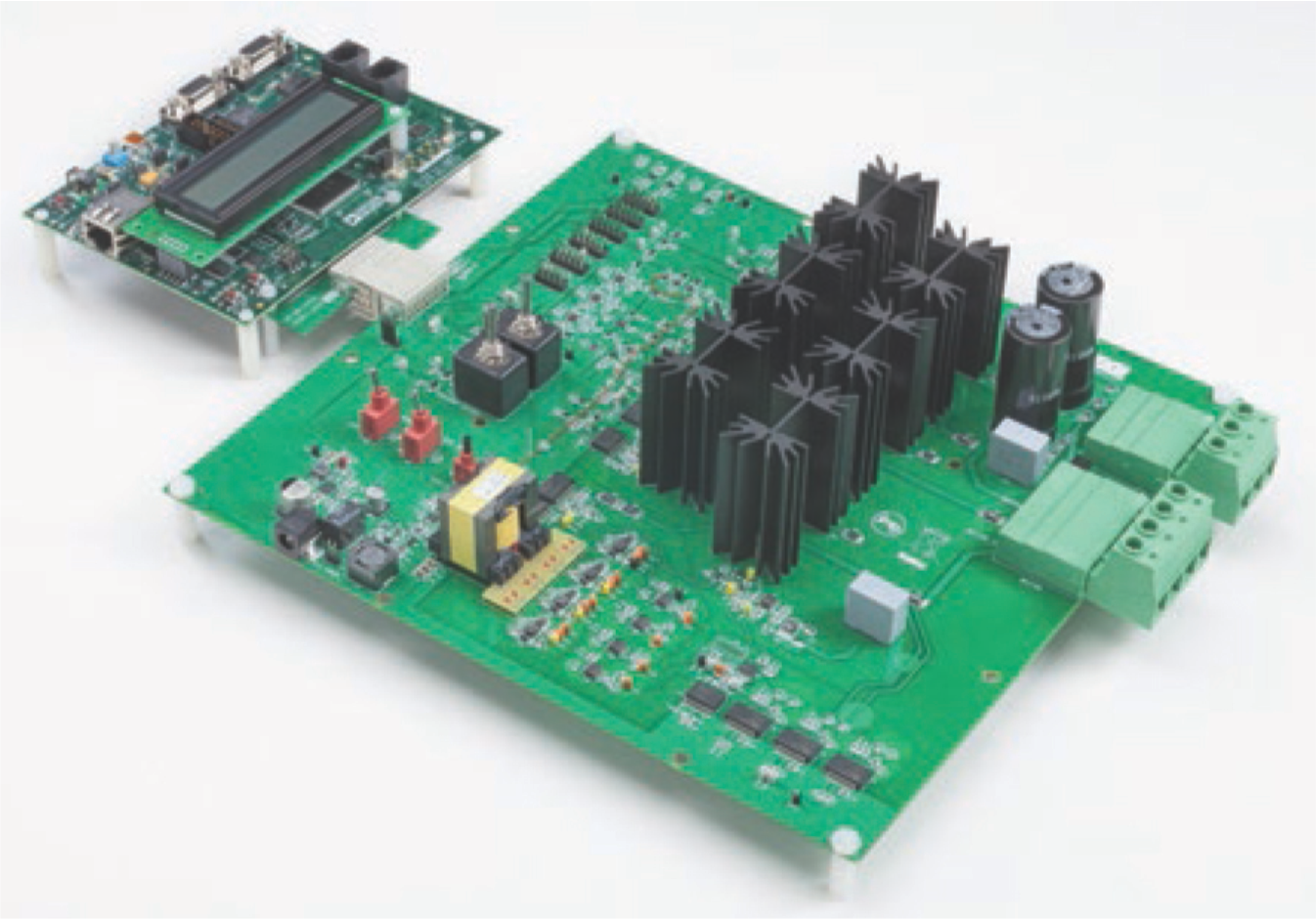
Short-circuit testing is carried out by manually switching a short-circuit between motor phases or between a motor phase and dc bus negative. The short-circuit to earth is not tested in this example. The controller and power boards are shown in Figure 5. These are the ADSP-CM408F EZ-kit6 and the EV-MCS-ISOINVEP-Z isolated inverter platform,7 both available from Analog Devices.
IGBT overcurrent and short-circuit protection are implemented using a range of methods in the experimental hardware. These are:
- DC bus current sensing (inverter shoot-through fault)
- Motor phase current sensing (motor winding faults)
- Gate driver desaturation detection (all faults)
For the dc bus current sensing circuit, a small filter must be added in order to avoid false tripping, since the dc bus current is discontinuous with potentially high noise content. An RC filter with 3 μs time constant is utilized. Having detected the overcurrent, the remaining delays to IGBT shutdown are delays through the op amp, comparator, signal isolator, trip response time in ADSP-CM408F, and gate driver propagation delay. These amount to an additional 0.4 μs, resulting in a total fault-to-turn off time delay of 3.4 μs—well within the short-circuit time constant of many IGBTs. Similar timing applies to motor phase current sensing using the AD7403 in conjunction with the integrated overload detection sinc filters on the ADSP-CM408F processor.
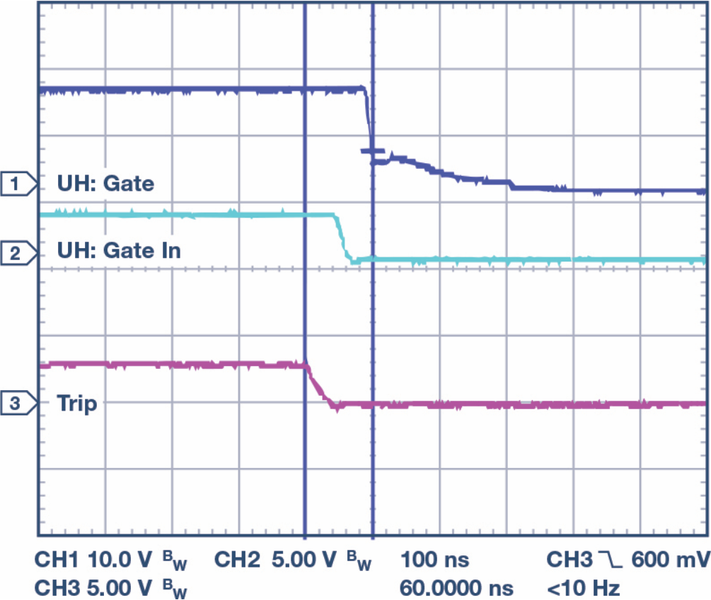
Along with the reaction time of the current sense circuitry or digital fast filters, the very short propagation delay of the ADuM4135 in both instances is critical to achieving viable fast overcurrent protection using either of these methods. In Figure 6, the delay between the hardware trip signal, the PWM output signal, and the actual gate-emitter waveform of the upper IGBT in one of the inverter legs is shown. The total delay to commencement of IGBT turn-off is seen to be around 100 ns.
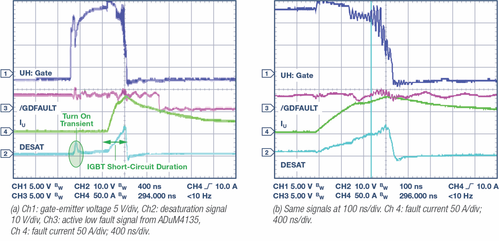
Gate driver desaturation detection can act significantly faster than the overcurrent detection methods described previously, and is important for limiting the extent to which short-circuit currents are allowed to rise, thus enhancing overall system reliability beyond the levels achievable even with fast overcurrent protection. This is illustrated in Figure 7. As the fault occurs the current starts to increase rapidly—in reality the current is much higher than shown as the measurement is taken with a bandwidth limited 20 A current probe for illustration only. The desaturation voltage reaches the 9 V trip level and the gate driver begins to shut down. It is evident that the entire duration of the short-circuit is <400 ns. The long tail on the current is the decay of the inductive energy by current freewheeling in the antiparallel diode of the lower IGBT.
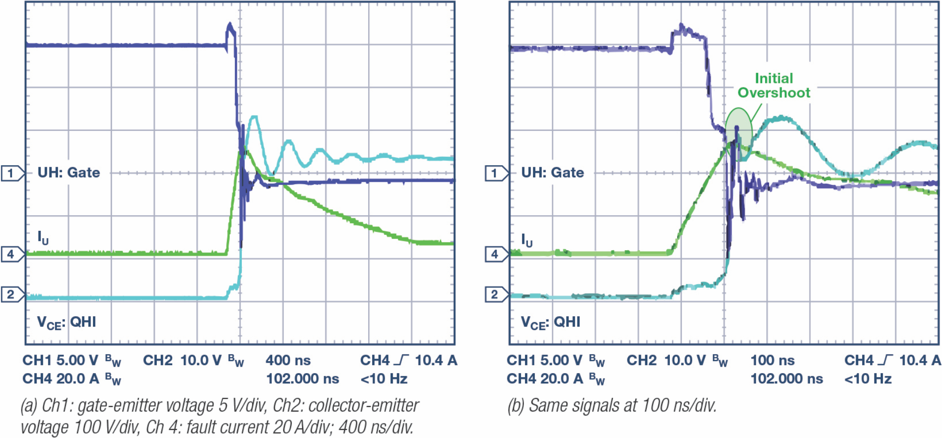
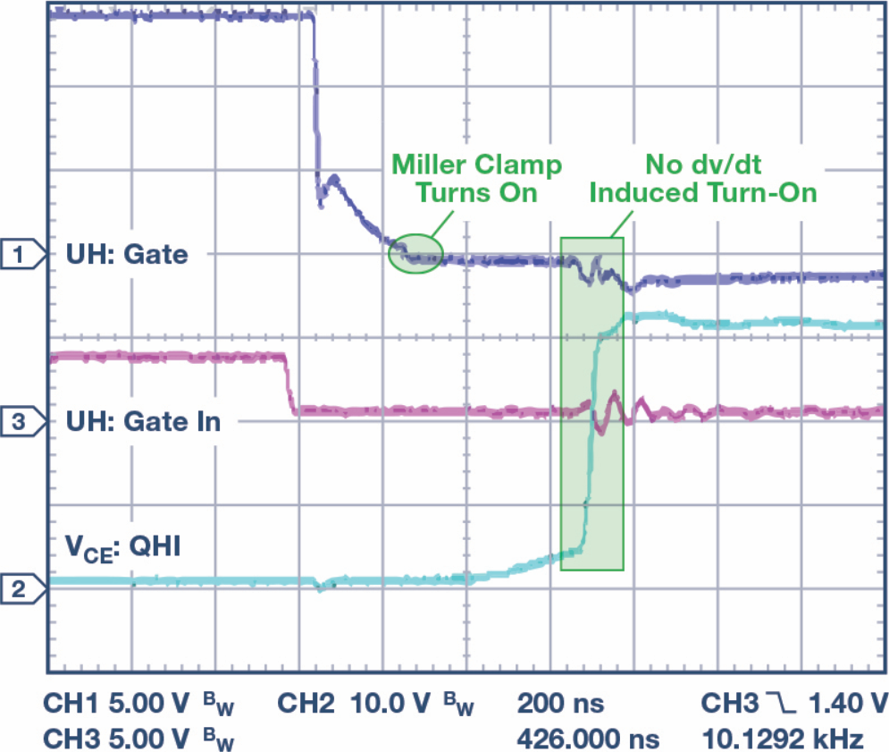
The value of Miller clamping in preventing inverter shoot-through in normal operation is illustrated in Figure 9.
Summary
Overcurrent and short-circuit detection and turn-off in a very short time period are becoming ever more important as the short-circuit withstand time of IGBT decreases down to 1 μs levels. Industrial motor drive reliability is strongly linked to the IGBT protection circuits. This article has outlined some approaches to handling this issue, and has presented experimental results that underline the value of robust isolated gate driver ICs such as the ADuM4135 from Analog Devices.