


Timers are a common peripheral in microcontrollers (MCUs), including PIC MCUs. With so many possible choices, how do you select the right one to use in your application?
Exploring the Versatile World of Microcontroller (MCU) Timers: Applications and Selection Guide
Timers are a ubiquitous peripheral in MCUs. It should come as no surprise that there are a lot of timers, each with their own use case that they excel at. Some timers are designed to be used as part of waveform generation, while others are ideal for pulse counting. In many cases, there is no wrong choice—instead, it will depend on the requirements and resources available. For more information about the timers, please see the linked peripheral pages in the table below.


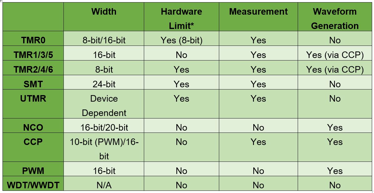 *Hardware limit refers to the ability to rollover at an arbitrary value, rather than the maximum count possible. (E.g.: 0x1000 versus 0xFFFF for a 16-bit timer)
Timer 0 (TMR0)
TMR0 can function in 8-bit or 16-bit mode. When in 8-bit mode, the high and low byte of the timer are independent of each other. The timer rolls over when the value set in the high byte matches the low byte. 16-bit mode is a free running timer, where the timer will rollover when it reaches the value 0xFFFF. To prevent data corruption during read/writes, the register is buffered, and only latched on the low byte.
Timer 1/3/5/… (TMR1)
TMR1 is a 16-bit gated timer with support for both synchronous and asynchronous clock signals. When TMR1 is in asynchronous mode, the timer functions in sleep and can generate an interrupt to wake the microcontroller. The timer also contains a gating function which can be used to hold the current value. To prevent corruption when reading/writing the 16-bit value, the timer can be configured to buffer the counter. The data will be latched on the low byte.
Timer 2/4/6/… (TMR2)
TMR2 is an 8-bit timer that supports one-shot and monostable modes of operation. One-shot mode triggers the timer, then clears the ON bit after reaching the hardware limit. Monostable functions identically to the one-shot mode, except that the ON bit remains set and the timer can be retriggered. TMR2 can be reset or triggered by an external signal.
Signal Measurement Timer (SMT)
The SMT is a large 24-bit timer that supports the following modes:
- (Windowed/Gated) Counter
- Capture
- Time of Flight
- (Gated) Window Measurement
- High and Low Measurement
- Period and Duty Cycle Measurement
- (Gated) Timer
Note: Values in parentheses are other modes available, e.g.: Windowed Counter, Gated Counter and Counter are all valid modes.
To support these operating modes, the SMT contains four 24-bit registers. The exact behavior of the registers depends on the mode.
Universal Timer (UTMR)
The UTMR is composed of two timer modules that can operate independently of each other, or as one larger timer. The size of the UTMR may vary by device; currently on the PIC18-Q71 family, it is 16-bit per module, or 32-bits if chained together. This timer was designed to contain the functionalities of all legacy timers (TMR0, TMR1 and TMR2).
The UTMR supports both synchronous and non-synchronous clock sources and allows for reading the current count without stopping the timer, even with non-synchronous sources. To control the timer, there are three configurable events: Start, Reset and Stop.
Start events define what starts the timer. The reset event defines what resets the count back to zero. And there is a stop event, which defines what will stop the timer completely. These events can be always enabled, triggered from an input signal or disabled entirely. This enables features like monostable triggering, hardware limits and one-shot operation.
Numerically Controlled Oscillator (NCO)
Note: The size of the NCO (16-bits or 20-bits) may vary, depending on device family.
The NCO is designed to generate a periodic waveform by adding a programmable increment to an accumulated total. When the total overflows, the overflow is kept, and a pulse is generated. The pulse can be a fixed number of input clock cycles in width, or it can be 50% output at the cost of halving the output frequency. While the NCO isn’t designed for measurement, it can be used if the NCO is stopped, read and then restarted.
Capture/Compare/PWM (CCP)
The CCP has three modes—Capture, Compare or Pulse Width Modulation (PWM). The Capture/Compare modes utilize TMR1 while PWM utilizes TMR2.
The Capture mode stores the value in TMR1 when a rising or falling event occurs (depending on operating mode). The Compare mode generates an output when the value in TMR1 matches the set value in the CCP. For PWM mode, TMR2 is 8-bit, but the CCP extends it to 10-bit using the internal oscillator’s prescaler bits.
PWM
Note: For PWM that depends on TMR2, see the CCP section.
The 16-bit PWM peripheral is fully standalone—meaning that it does not utilize another system timer, unlike CCP (which depends on TMR2). There are five operating modes for generating PWM:
- Left Aligned
- Right Aligned
- Center-Aligned
- Variable Aligned
- Compare
These modes change how the count is used to generate the output. Inside of each instance are slices, each containing two outputs. The outputs share a common frequency but have their own duty cycle registers. Additionally, the peripheral is double buffered for smooth output changes and can be synchronized with other PWM instances.
Watchdog Timer (WDT)/Windowed Watchdog Timer (WWDT)
The WWDT is a special timer designed to detect a deadlock in the microcontroller. A WWDT is a timer that runs the background. Periodically, software must clear it through a special sequence, or it will reset the microcontroller. WDT and WWDT differ only in that the WWDT has a “Window” feature. The “Window” feature can require the clearing sequence to be performed within a certain time window, rather than any time before the timer rolls over. This prevents a deadlock from being undetected by clearing the timer continuously.
Selecting the Timer and Learning More
After understanding the timer peripherals, select which timer closest matches the features needed in the application. In many cases, there are multiple possible timers that can perform the task. In this case, select the simplest timer—this leaves timers with more capabilities available for future use. The device datasheet, application notes and technical briefs go into more detail on how all of these timers operate and the registers associated with them. Code examples that use a specific timer can be found by searching MPLAB Discover.