


Introduction
The increase of voltage input rails for delivering point-of-load power to DSPs, ASICs, FPGAs and microprocessors is creating more challenges for power supply designers. Especially as system power and operating frequency demands continue to grow, causing infrastructure, industrial and factory automation equipment to be more sensitive to noises and several unforeseeable events. For example, false inputs at start up can trigger system latch up, reliability issues, and even system failure.


This article discusses how to configure various voltage output tracking and sequencing options for an FPGA or microprocessor that will enable the proper start up and shut down of sensitive multi-rail systems. We’ll also check out a ratiometric and coincidental setting that prevents an FPGA’s internal electrostatic discharge (ESD) diodes from biasing or being overstressed during rising or falling outputs. These configurations will improve system reliability, which is vital to the productivity and uptime of infrastructure systems and factory floor industrial equipment.
System Configuration
A typical application circuit configuration for an FPGA is shown in Figure 1. From the highest input rail of 3.3V to the second input rail of 2.5V, we find back-to-back ESD diodes serving as internal protection circuits. Then another set of back-to-back ESD diodes is configured from the second input rail to the third rail.
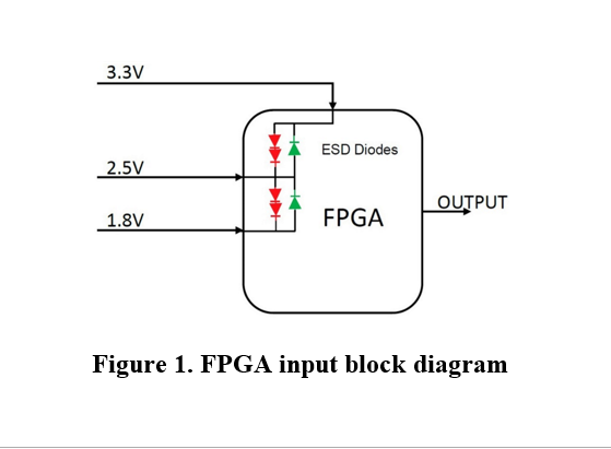 Let’s assume a case where the highest input rail, which is the 3.3V in this example, starts up first before any other rails. It then pre-biases the 2.5V output rails to approximately 1.9V and the 1.8V rail to 1.2V. Similarly, the 1.8V rail pre-biases the 2.5V and the 3.3V rail if it come up first. In either case, the ESD diodes must conduct during start up. Figure 2 illustrates the voltage signals of the input rails for 3.3V and the signal it will send to the 2.5V before it is active. The charging current through the ESD diodes depends on the start-up slew rate, the 2.5V output capacitances, and any loading. Running the same start up scenario with the 1.8V output rail will exhibit similar voltage signals.
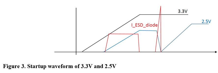
 Each time the ESD diodes conduct, their reliability is degraded. Figure 3 illustrates what happens to the 3.3V and 2.5V rails when the 2.5V input source is not rated for pre-biased start up. As you can see, the FPGA’s internal ESD diodes are stressed when the 2.5V rail starts up. Therefore, using a power source that is rated with pre-biased start up avoids this problem and averts the potential for system latch up. Step-down regulators with correctly configured output power tracking will ensure that all of your system rails properly soft-start together and prevent the ESD diodes from conducting. This simple step will improve system reliability and avoid any unforeseen system power latching.
Integrated FET DC/DC Converters
Presented in Figure 4 is a typical application circuit for a 2A DC/DC converter with a 2.7V to 5.5V input voltage range. Only a few external components, including resistors, capacitors and inductor are required. The converter integrates the compensation and the power MOSFETs to guarantee design robustness, minimum part counts, and high efficiency up to 95%.
 The converter’s Pin 5 provides both soft-start (SS) and output tracking (TR) functions. When this pin is connected high, the soft-start time is internally set to 1ms. However, various soft-start schemes can be achieved using external components. Figure 5 illustrates how the SS/TR feature is used to program external soft-start time.
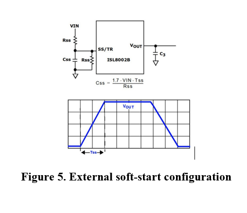 Simply set the soft-start resistor RSS and capacitor CSS to adjust the time. The approximate relationship is shown in Equation 1:
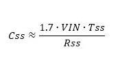 Equation 1.
This soft-start feature can also be configured for tracking other outputs. Figure 6 shows a ratiometric tracking configuration of VOUT1 to VOUT2.
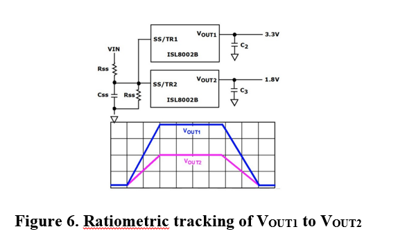 In addition, you can connect the two SS/TR together to force the two output voltages to rise at the same time. Similarly, the shutdown function also tracks each other ratiometrically, as with the soft-start time described in Equation 1.
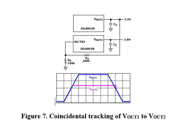
Coincidental tracking can be configured as shown in Figure 7. Simply add a resistive divider that is the same ratio as its output voltage sense divider in the feedback loop. In this case, all the output voltages ramp up with the same voltage and slew rate according to the main rail. Typically, the highest rail is what all other outputs should track to. Then each output will branch out as they reach their regulation point. By having all the output rails start up and shut down in a well-controlled fashion, you will prevent the Figure 1 internal ESD diodes from conducting or from being forward biased. Most importantly, this design technique prevents any degradation in system reliability, latch up conditions, or worse – system failures in the field.
 Conclusion
Integrated FET step-down regulators, like the ISL8002B, offer numerous easy to apply solutions for tracking voltages during power up and power down sequencing. Nearly any system voltage tracking requirement can be configured with one of the block circuits discussed in this article. These configurations are not limited to two regulators, as they can be applied to any number of rails within your system. Simply connect all the SS/TR pins together for ratiometric tracking. Alternately, you can use a resistive divider to program the system for coincidental tracking. Either the ratiometric or coincidental tracking method will prevent unnecessary stress across the ESD diodes to improve your system’s overall reliability.
Courtesy: www.renesas.com