MOSFETs to work in Continuous Conduction Mode (CCM) in Totem Pole PFC topologies.)
Tougher CO2 emission standards along with changing public and corporate opinions are accelerating the development of electric vehicles (EV) worldwide. This creates enormous growth for On Board Chargers (OBC) in the coming years with an estimated compound annual growth rate (CAGR(TAM)) of 37.6% or higher based on recent trends through the 2024 calendar year. For global automotive that are designing the OBC module, improving the system efficiency or defining a new topology that is also highly reliable has become an urgent challenge.
A simple power factor correction (PFC) topology for single-phase input AC systems (Fig.1) is a traditional single-channel boost converter. This solution contains a diode full-bridge for input AC rectification and a PFC controller to increase the power factor of the load, which improves efficiency and reduces harmonics imposed upon the AC input power source. The advantages of this popular PFC boost topology are ease of design, low implementation costs and reliable performance. However, conduction losses of the diode bridge rectifier are inevitable, and this will not support bidirectional operation that allows a vehicle to provide power back to the AC power grid. Using a multi-channel interleaved traditional boost converter with multiple iterations of the boost circuit can improve some system performance parameters but it does not remove the need for the input diode bridge.


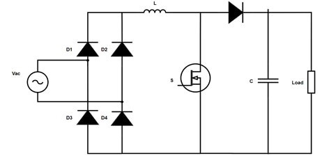
Fig.1 Conventional PFC
The simulation data (Fig.2) indicates that the power loss of the input diode bridge dominates over all other component losses in the PFC block.
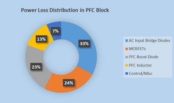
Fig.2 Power Loss Distribution in PFC
In order to improve OBC system efficiency, different PFC topologies have been studied including traditional PFC, semi-bridgeless PFC, bidirectional bridgeless PFC and Totem Pole bridgeless PFC. Among those, Totem Pole PFC (Fig.3) has risen in popularity due to its reduced component count, low conduction losses and high efficiency.
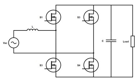
Fig.3 Bridgeless Totem Pole PFC
It is difficult for conventional Silicon (Si) MOSFETs to work in Continuous Conduction Mode (CCM) in Totem Pole PFC topologies because of the poor reverse recovery characteristics of the body diode. Silicon Carbide (SiC) MOSFETs use a completely new technology that provides superior switching performance, minimal reverse recovery time, low RDS(on) and higher reliability compared to Si MOSFETs.In addition, the compact chip size ensures low capacitance and low gate charge (QG) for the device.
Another challenge for designing OBC is that there is limited space allocated in the vehicle for the module. While power requirements and battery voltages are increasing, it is becoming more difficult to design an OBC that meets the mechanical size requirements while delivering the required output power. Engineers have had to tolerate trade-offs between power, size and efficiency with the current technologies used for OBC, but SiC is breaking down these design barriers. Engineers using SiC with higher switching frequencies can use smaller inductors and still achieve the same inductor ripple current requirements they had before.
The benefits of using SiC MOSFETs in the OBC systems are ability to switch at higher frequencies, increased power density, higher efficiencies, EMI performance improvement and system size reduction. Now that SiC is widely available, engineers can use Totem Pole PFC in their designs to improve performance.
The newly released 6.6kW Totem Pole PFC for OBC evaluation board provides a reference design for a multi-channel interleaved bridgeless Totem Pole PFC topology. This design consists of an isolated high current, high-efficiency IGBT driver (NCV57000DWR2G) and two high-performance SiC MOSFETs (NVHL060N090SC1) in each high-speed leg. Additionally, the low-speed leg uses two 650V N-Channel power MOSFET SUPERFET® III (NVHL025N65S3) devices controlled by a monolithic high and low side gate-driver IC (FAN7191_F085).
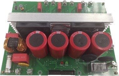
Figure 4. 6.6kW Interleaved Totem Pole PFC Evaluation Board
With these high-performance SiC MOSFETs configured in a Totem Pole topology, the system achieves 97% efficiency (typical). The design includes hardware Over-Current Protection (OCP), hardware Over-Voltage Protection (OVP) and an auxiliary power distribution system (non-isolated) that can supply every circuit on the PFC board and the control board without another DC source. Flexible control interfaces are available to adapt to a variety of control boards.
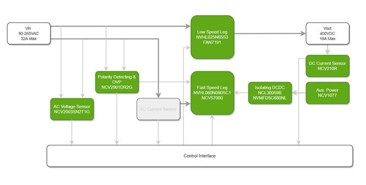
Figure 5. 6.6kW Interleaved Totem Pole PFC Evaluation Board Block Diagram