to a DC bus supply which acts as the input to the DC/AC inverter stage.)
Courtesy: Analog Devices
The block diagram is expanded in more detail in Fig. 1 below, where the different parts of the drive as well as the various external interfaces to the motor, encoder, and external networks are shown, as well as the power and data flows between the different elements. Every drive architecture is slightly different, particularly in terms of how electrical isolation between the high voltage zone and the Safety Extra Low Voltage (SELV) zone is managed, but the architecture shown in Fig.1 is quite common.


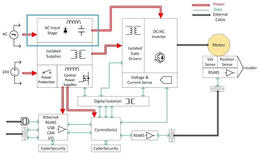
The block under more detailed consideration in this blog is the AC input stage. As shown in Fig.1, the AC input stage is the main power path from the AC grid supply to the DC/AC inverter stage. This blog discusses the different functions performed by this block, namely:
- AC/DC Conversion
- EMI Filtering
- Inrush Protection
- Transient Protection
The main purpose of the rectifier is to convert the mains AC input (1-phase or 3-phase) to a DC bus supply which acts as the input to the DC/AC inverter stage. This is generally achieved through a six-diode bridge rectifier, followed by a large electrolytic capacitor bank across the DC bus, which provides smoothing for the rectified AC signal, and renders it more DC-like, effectively acting as a large low-pass filter. The amount of “ripple” present on the DC bus is directly proportional to the size of the DC bus capacitor bank, which must also be sized to provide holdup of the drive during short AC mains dropout events. Some variable speed drives implement fully controlled AC/DC converters, that use power switches rather than power diodes – these allow for full control of the input AC current, to manage low-frequency harmonics. However, these are much more expensive and are not required in the majority of applications.
The AC/DC rectifier stage is also important in that it helps ensure that the drive complies with conducted EMI regulations such as EN61000-3-2, which is published by the International Electrotechnical Commission (IEC). The DC/AC inverter is a switching converter with many fast transient voltages and currents which result in significant differential and common mode high-frequency currents through parasitic inductances and capacitances, and these must be prevented from polluting the AC network and impacting other equipment. Input EMI filtering is typically implemented using a mix of differential and common mode chokes, and a mix of high-frequency bypass capacitors between the AC lines (known as X-capacitors) and between the AC lines and earth (known as Y-capacitors). These components present a high series impedance to high-frequency currents and a low impedance to earth for these high-frequency currents.
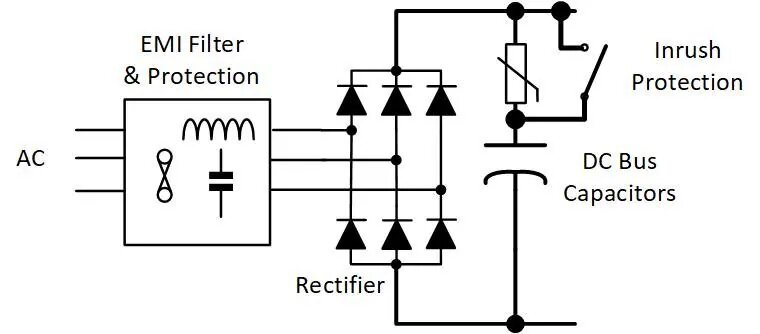
Inrush protection is another important function carried out by the input AC/DC stage. On startup, the DC bus capacitor bank is completely discharged, and the charging current from the AC line voltage to the DC bus is limited only by the resistive impedance of the EMI filter chokes and bridge diodes. Without some additional current limiting, a very high transient charging current will flow from the AC line to the DC bus capacitor bank, and this can result in overload in the filter components and/or the recToes. To counteract this, a series thermistor is sometimes inserted in the charging path – this has high resistance when it is cold, and this limits the charging current to a reasonable level. Once it heats up, the resistance reduces dramatically, limiting the power losses. The one issue with this style of inrush protection is related to multiple restarts in close proximity – in this case, the thermistor will not have cooled down enough in between restarts and damaging over-currents can occur. A better solution is to use a standard current limiting resistor, with a relay or solid-state switch in parallel, that can be turned on once the inrush period is over, as illustrated in Fig. 2.
Last, but not least, transient voltage protection is a critical function performed by the input AC/DC stage. Transient voltage spikes and surges can be present on the AC grid for mcans, and these have the capacity to permanently damage a motor drive. In order to counteract this, components such as Transient Voltage Suppressors (TVS) diodes or Metal Oxide Varistors (MOV) are generally inserted in parallel with the AC line phases. These act to clamp any voltage spikes and absorb the energy associated with them, and in so doing protect the rest of the electronics.
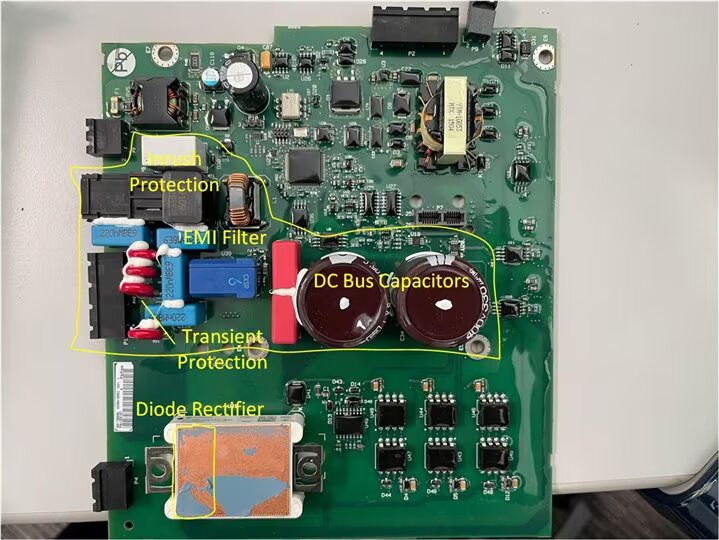
These various elements of the AC input stage are shown in Fig.3 inside a Rockwell motor drive. Even though they are relatively simple components, electronically speaking, they take up a large area within a motor drive and have a large impact on the overall reliability, protection, and lifetime of the drive.