


 analog-to-digital converters (ADCs) use various new techniques for improved resolution. Understanding how these devices work is important in preventing malfunction and erroneous issues. This application note discusses)
Introduction
Successive approximation register (SAR) analog-to-digital converters (ADCs) use various new techniques for improved resolution. Understanding how these devices work is important in preventing malfunction and erroneous issues. This application note discusses in general the pitfalls that occur regularly when using SAR ADCs and, more importantly, how to easily prevent them.


How do PulSARs work?
The Analog Devices, Inc., PulSAR family of ADCs uses internal switched capacitor techniques to extend the resolution of SAR ADCs to 18 bits. This means that on a CMOS process, the need for expensive thin film laser trimming is not required.
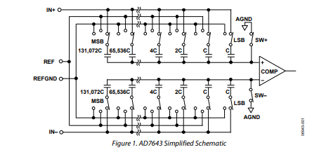
A simplified input stage of the AD7643 is shown in Figure 1.
The AD7643, an 18-bit ADC, capable of converting 1.25 MSPS, is based on a charge-redistribution digital-to-analog converter (DAC), which is popular in the newer SAR ADCs. The SAR algorithm takes two phases to determine the ADC output code. The first phase is the acquisition phase, where the SW+ and SW− are initially closed. All switches are connected to the IN+ and IN− analog inputs, thus each capacitor is used as a sampling capacitor acquiring the analog signal at the input. The second phase is the conversion phase where the SW+ and SW− are open. The inputs are disconnected from the internal capacitors and applied to the comparator inputs. This results in an unstable comparator. Without detailing the SAR algorithm, switching each element of the array between REF and REFGND starting with the MSB, brings the comparator back into a balanced condition and thus generates the output code representing the analog input signal.
AN-931
Reference
On analyzing the reference section of Figure 1, focusing on what pitfalls can be found when designing circuits using PulSAR ADCs, notice that the inputs are disconnected from the internals of the ADC when calculating the output code. This is an important point. It means that any noise that occurs at the inputs (IN+ and IN−) during the conversion phase does not affect the resultant output code.
During the conversion phase, the REF pin is connected to the internal switched capacitor structure, as there is no sample-and hold circuit at the reference input. Any noise occurring here (during the conversion phase) has a direct effect on the output code. If one of the bits is incorrectly set, for example, if Bit 6 is set to a 1 when it should have been a 0, due to increased noise during that bit trial then all of the following bits will be set to 1 to try to reduce the DAC output to the correct value. Thus, an incorrect output is calculated and results in a series of 1’s on the lower 6 bits on the output code, often referred to as stuck bits. To avoid stuck bits, a very stable reference is crucial.
What Type of Precision Reference can be used?
One misconception that appears in the Specifications section in the PulSAR data sheets is the external reference and current drain. Typically, this value ranges from a few tens of μA, for low throughput PulSAR (AD7685 @ 250 kSPS) and can be up to a few hundred μA for faster throughput PulSAR (AD7621 @ 3 MSPS). This is the average current, with the converter inputs driven such that the reference driving circuit delivers the maximum current the ADC requires. This can be −FS or +FS depending on the ADC. Practically any reference can supply even a few hundred μA, but these are not practical in a PulSAR high resolution converter.
Low Power References (ADR12x, ADR36x)
Low power references are usually unacceptable because they typically lack the ability to settle during the heavier weighted, most significant bit (MSB) decisions. These references typically have larger output impedances than the buffered counterparts such as AD780, ADR43x, and ADR44x references. The dynamics of the reference circuit are basically an RLC tank circuit in which R is internal to the ADC (some series switch resistances), C is the reference storage or decoupling capacitor, and L is the inductance from the reference itself. The designers of PulSAR ADCs chose a certain set of R and C to work with, given an idea of L from a precision voltage reference, such as the AD780. These values were used such that the system is critically damped when excited (this excitation occurs during the bit decision process). Using a low power reference with a much higher inductance (100× or more than a good buffered reference) causes the RLC circuit to become under-damped and causes the behaviour of stuck bits as previously detailed.
The behaviour of some low power references is shown in Figure 2 to Figure 7. Note that in these figures the term burst mode is a mode in which the conversion control signal is inactive until an instant where 8192 samples are taken. This is the worst- case demand for the reference because when the ADC is not converting, there are no dynamics present to the reference. The AD7686, 16-bit, 500 kSPS PulSAR was used to develop the data in Figure 2 to Figure 7.
Traditionally, dc measurements are plotted in a histogram of data which can be very meaningful to show the code transitions (or transition noise) and peak-to-peak noise. However, Figure 2 and Figure 3 are shown in the time domain to prove the theory that the references tested cannot settle during the dynamic SAR conversion.

Figure 2 shows a classic example of an under-damped RLC circuit in a burst mode of operation. Figure 3 shows continuous mode and as indicated by both of these figures, this reference never quite settles to a 16-bit performance. In a continuous mode, the peak-to-peak output codes still deviate ~16 counts or ~4× of the performance specified in the AD7686 data sheet.
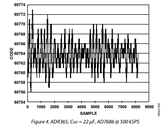 Figure 4 shows the performance of the AD7686 using the ADR365. There is no real difference between burst mode or continuous mode with this reference—it never quite settles to anything at a 16-bit level either. The peak-to-peak output codes are also ~4× greater than the specified performance of the AD7686.
Buffering the Reference
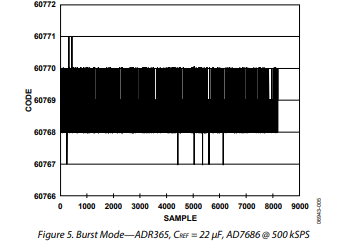
Buffering practically any reference with a suitable amplifier, such as the AD8031 or AD8605, allows sufficient drive capability because the dynamics are now present to the output of a higher bandwidth amplifier. Figure 5 shows the output for the ADR365 buffered with the AD8031 amplifier and tested as the reference to the AD7686.
Buffering the external reference brings up the original question of power requirement. Using a good reference with enough drive, such as the AD780, ADR43x, or ADR44x, is a simpler solution. Any of the low power references can be used in this scenario as these buffers have (typically) low series inductance. This can be useful in multiconverter systems because one buffer can be used to drive many PulSAR ADCs. Also, in multiconverter applications, the best approach is to use a star configuration for the reference trace, with each converter using its own reference storage capacitor. Daisy chaining from the first ADC in the group is not recommended as the ADCs reference can have crosstalk.
Low Power References (<10 kSPS Throughput)
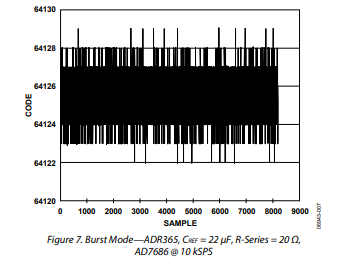
In low power, slower throughput applications (such as 10 kSPS or lower that must use a low power reference), a small series resistor can be used between the output of the reference to the ADC, for example, 10 Ω may suit. In a burst mode of operation, the first few conversions may need to be discarded as the current across this resistor stabilizes. For faster throughputs, bursting conversions typically cannot be done because there are too many discarded conversions. Also, as the current through the resistor increases to the steady-state value, the voltage drop across this resistor can be seen as a slope in the time domain. This is commonly referred to as reference sag.
Figure 6 shows this issue of reference sag when using a series resistor of 20 Ω in a faster application of 500 kSPS. Note the under-damped situation for the first few hundred conversions and the slight negative slope as the samples increase.

Figure 7 shows a slower throughput of 10 kSPS. The underdamped issue is not present and the peak-to-peak noise is five counts, almost parallel in performance to the AD7686.
Why Use a large decoupling capacitor?
Now that a suitable reference has been selected (or a suitable reference and buffer circuit), the buffer (op amp) data sheet advises avoiding heavy capacitive loads. However, the PulSAR ADC requires a 10 μF or larger reference decoupling capacitor (REF CAP). These two requirements seem at first to contradict each other.
The term decoupling has different meanings especially when the user notices a value of 10 μF on the reference (REF) pin of the PulSAR ADC and other 10 μF capacitors on the power supplies (VDD, AVDD, DVDD, VIO, OVDD). The capacitor on REF is not a bypass capacitor—it is part of the SAR ADC that simply cannot fit on silicon. During the bit decision process, because the bits are settled in a few 10s of nanoseconds or faster, the storage capacitor (REF CAP, see Figure 8) is shown here to replenish the charge of the internal CDAC required to balance the comparator with the charge on the internal capacitor array. As the binary-bit-weighted process steps along, small chunks of charge are taken from this capacitor. Of course, the internal capacitor array is a fraction of the size (~15 pF to 60 pF, depending on the ADC), but these larger value storage capacitors are required to meet the SAR bit decision settling time. There are some intricate details as to what happens during the bit decision process regarding charge, however, this is beyond the scope of this application note.
An insufficient storage capacitor can also cause stuck bits. The placement and type of the capacitor are also significant. A low equivalent series resistance (ESR) capacitor is required to avoid reference sag. In recent years, very good ceramic X5R dielectric capacitors have become available with 10 μF values in 0603 case sizes. For many of the PulSAR ADCs, the reference capacitor value can be lowered with some performance degradation, namely in DNL.
Layout
It is recommended that a capacitor be placed directly at the reference pins of the ADC. This is recommended to eliminate the switch capacitor transients. A good quality capacitor is required (for example, a tantalum or a X5R type ceramic; an NPO would not be recommended). Because this is a charge storage capacitor as opposed to a bypass capacitor, values in the range of 4.7 μF to ~22 μF can be used. Note that a turn-on settling time is specified in some data sheets, where a particular reference capacitance value is used at the REF pin. Refer to the Specification section of the relevant PulSAR data sheet for information.
At the start of the layout, consider a PCB layout with a SAR ADC device and consider placing a capacitor at the ADC reference pins. Place the capacitor close to these pins first, then place the reference close to the capacitor, then close to the amplifiers (see Figure 8).

A thick trace is also required in the layout to reduce any impedance in the circuit. The dynamic input impedance of the reference input of the ADC means that the input to this pin must be driven with a low impedance source. Note that if the reference is buffered entering the REF pin, then the buffer output impedance must be low. This also applies to the analog input pins.
Amplifier Choices
Most of the PulSAR data sheets describe the amplifiers in detail. Some of the main issues to be aware of are low noise levels and low output impedance. The input signal settling time is also an important parameter, thus high slew rate performance is required on the amplifier. Some amplifiers that fit this choice are the following: ADA4841-1, AD8021, ADA4899-1, AD8099, and ADA4941-1.
The ADA4841-1 and the AD8021 are excellent choices for an ADC driver with PulSAR ADCs, high bandwidth, and good slew rate. The ADA4899-1 is also a good alternative with an excellent slew rate and good bandwidth, but has the added expenses of consuming more current. There are also other options that may suit various applications like the AD8099, which may fit an 18-bit ADC application due to a very low noise density. However, this device is not unity gain stable and although it can be configured to do so, it is a high consumer of current at 16 mA. However, it does have a DISABLE function that can be used to turn down the current consumption for portable applications. The ADA4941-1 is also another option for single-to-differential applications, for example, the PulSAR 18-bit ADC, with a 5 V input range.
Conclusion
Understanding how SAR ADCs work is very important to understanding the pitfalls of a new design. Those pitfalls listed in this application note are the popular issues seen on new designs.
Article Courtesy: Analog Devices Inc.
www.analog.com/ADCs.