

Introduction
Many machine vision applications now require high-resolution 3D depth images to replace or augment standard 2D imaging. These solutions rely on the 3D camera to provide reliable depth information to guarantee safety, especially when machines are operating in close proximity to humans. The cameras also need to provide reliable depth information while operating in challenging environments, such as in large spaces with highly reflective surfaces and in the presence of other moving objects. Many products to date have used low-resolution range-finder type solutions to provide depth information to augment 2D imaging. However, this approach has many limitations. For applications that benefit from higher resolution 3D depth information, CW CMOS ToF cameras provide the highest performance solutions on the market. Some of the system’s features enabled by high-resolution CW ToF sensor technology are described in more detail in Table 1. These system features also translate to consumer use cases such as video bokeh, facial authentication, and measurement applications, as well as automotive use cases such as driver alertness monitoring and automated in-cabin configuration.


Table 1. Continuous Wave Time of Flight System Features
| System Feature | Enablers |
| Depth precision and accuracy | • Modulation frequency
• Modulation schemes and depth processing |
| Dynamic range | • Readout noise
• Raw frame rate |
| Ease of use | • Calibration procedure
• Temperature compensation • Eye-safety monitoring |
| Outdoor operation | • Sensitivity at 940 nm
• Illumination power and efficiency |
| 2D/3D fusion | • Pixel size
• Depth and 2D IR images |
| Multisystem operation | • In-pixel cancellation of interfering light
• Camera synchronization |
Continuous Wave CMOS Time of Flight Camera Overview
A depth camera is a camera where each pixel outputs the distance between the camera and the scene. One technique to measure depth is to calculate the time it takes for the light to travel from a light source on the camera to a reflective surface and back to the camera. This travel time is commonly referred to as the time of flight (ToF).
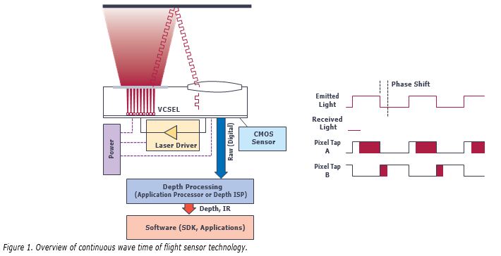
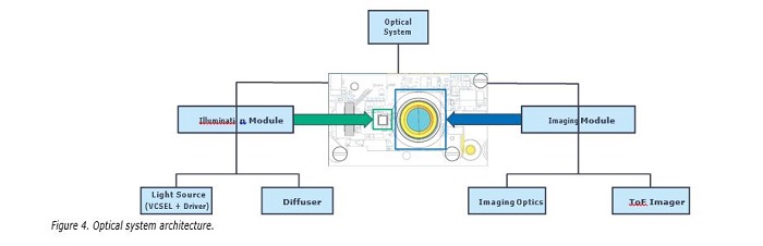
A ToF camera is comprised of several elements (see Figure 1) including:
a light source—such as a vertical-cavity surface-emitting laser (VCSEL) or edge-emitting laser diode—that emits light in the near-infrared domain. The most commonly used wavelengths are 850 nm and 940 nm. The light source is usually a diffuse source (flood illumination) that emits a beam of light with a certain divergence (aka, field of illumination or FOI) to illuminate the scene in front of the camera.
- a laser driver that modulates the intensity of the light emitted by the light source.
- a sensor with a pixel array that collects the returning light from the scene and outputs values for each pixel.
- a lens that focuses the returning light on the sensor array.
- a band-pass filter co-located with the lens that filters out light outside of a narrow bandwidth around the light source wavelength.
- is a processing algorithm that converts output raw frames from the sensor into depth images or point clouds.
One can use multiple approaches to modulate the light in a ToF camera. A simple approach is to use a continuous wave modulation—for example, a square wave modulation with 50% duty cycle. In practice, the laser waveform is rarely a perfect square wave and may look closer to a sine wave. A square laser waveform yields better signal-to-noise ratio for a given optical power, but also introduces depth nonlinearity errors due to the presence of high-frequency harmonics.
A CW ToF camera measures the time difference td between the emitted signal and the return signal by estimating the phase offset ϕ = 2πftd between the fundamentals of those two signals. The depth can be estimated from the phase offset (ϕ) and speed of light (c) using:
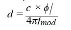
where fmod is the modulation frequency.
A clock generation circuit in the sensor controls the complementary pixel clocks that respectively control the accumulation of photo-charges in the two charge storage elements (Tap A and Tap B), as well as the laser modulation signal to the
laser driver. The phase of the returning modulated light can be measured relative to the phase of the pixel clocks (see right side of Figure 1). The differential the returning modulated light and to the phase of the returning modulated light relative to the pixel clock.
Using principles of homodyne detection, a measurement is made with multiple relative phases between pixel clock and laser modulation signal. These measurements are combined to determine the phase of the fundamental in the returning modulated light signal. Knowing this phase allows calculation of the time it takes the light to travel from the light source to the object being observed and back to the sensor pixel.
Advantages of High Modulation Frequencies
In practice, there are nonidealities such as photon shot noise, readout circuit noise, and multipath interference that can cause errors in the phase measurement. Having a high modulation frequency reduces the impact of those errors on the depth estimation.
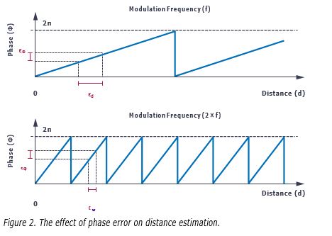
This is easy to understand by taking a simple example where there is a phase error ϵϕ—that is, the phase measured by the sensor is ϕ̂ = ϕ + ϵϕ. The depth error is then:
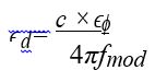
Therefore, the depth error is inversely proportional to the modulation frequency, fmod. This is illustrated graphically in Figure 2.
This simple formula explains in large part why ToF cameras with high modulation frequency have lower depth noise and smaller depth errors than ToF cameras with lower modulation frequency.
One drawback of using a high modulation frequency is that the phase wraps around faster, meaning the range that can be unambiguously measured is shorter. The common way to get around this limitation is to use multiple modulation frequencies that wrap around at different rates. The lowest modulation frequency provides a large range with no ambiguity but larger depth errors (noise, multipath interference, etc.), while higher modulation frequencies are used in tandem to reduce depth errors. An example of this scheme with three different modulation frequencies is shown in Figure 3. The final depth estimate is calculated by weighting the unwrapped phase estimates for the different modulation frequencies, with higher weights being assigned to the higher modulation frequencies.
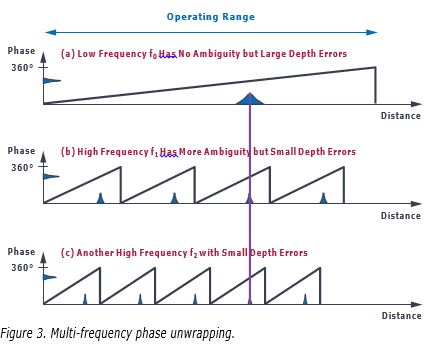
If the weights for each frequency are chosen optimally, the depth noise is inversely proportional to the root mean square (rms) of the modulation frequencies chosen in the system. For a constant depth noise budget, increasing the modulation frequencies enables reducing the integration time or the illumination power.
Other System Aspects Critical to Performance
There are numerous system features to consider when developing a high perfor- mance ToF camera, some of which are covered briefly here.
Image Sensor
The image sensor is a key component in a ToF camera. The effects of most depth estimation nonidealities (for example, bias, depth noise, and multipath artifacts) are reduced when the average modulation frequency of the system increases. It is therefore important that the sensor has a high demodulation contrast (ability to separate photoelectrons between Tap A and Tap B) at high
modulation frequency (hundreds of MHz). The sensor also needs to have a high quantum efficiency (QE) in the near-infrared wavelengths (for example, 850 nm and 940 nm), so that less optical power is needed to generate photoelectrons in the pixel. Finally, a low readout noise helps with the dynamic range of the camera by allowing to detection low return signals (far or low reflectivity objects).
Illumination
The laser driver modulates the light source (for example, VCSEL) at high modulation frequency. In order to maximize the amount of useful signal at the pixel for a given optical power, the optical waveform needs to have fast rise and fall times with clean edges. The combination of laser, laser driver, and PCB layout in the illumination subsystem are all critical to achieve this. There is also some characterization required to find the optimal optical power and duty cycle settings to maximize the amplitude of the fundamental in the Fourier transform of the modulation waveform. Finally, the optical power also needs to be delivered in a safe manner with some safety mechanisms built-in at the laser driver and system level to ensure Class 1 eye safety limits are respected at all times.
Optics
Optics plays a key role in ToF cameras. ToF cameras have certain distinct characteristics that drive special optics requirements. Firstly, the field of illumination of the light source should match the field of view of the lens for optimum efficiency. It is also important that the lens itself should have high aperture (low f/#) for better light collection efficiency. Large apertures can lead to other trade-offs around vignetting, shallow depth of field, and lens design complexity. A low chief ray angle lens design can also help reduce the band-pass filter bandwidth, which improves ambient light rejection and therefore improves outdoor performance. The optical subsystem should also be optimized for the desired wavelength of operation (for example, anti-reflective coatings, band-pass filter design, lens design) to maximize throughput efficiency and minimize stray light. There are also many mechanical requirements to ensure optical alignment is within the desired tolerances for the end application.
Power Management
Power management is also critically important in a high-performance 3D ToF camera module design. The laser modulation and pixel modulation generate short bursts of high peak currents, which places some constraints on the power management solution. There are some features at the sensor integrated circuit (IC) level that can help reduce the peak power consumption of the imager. There are also power management techniques that can be applied at the system level to help ease the requirements on the power source (for example, battery or USB). The main analog supplies for a ToF imager typically require a regulator with good transient response and low noise.
Depth Processing Algorithm
Finally, another large part of the system-level design is the depth processing algorithm. The ToF image sensor outputs raw pixel data from which the phase information needs to be extracted. This operation requires different steps that include noise filtering and phase unwrapping. The output of the phase unwrapping block is a measurement of the distance travelled by the light from the laser, to the scene, and back to the pixel, often called range or radial distance.
The radial distance is generally converted into point cloud information, which represents the information for a particular pixel by its real-world coordinates (X,Y,Z). Often, end applications only use the Z image map (depth map) instead of the full point cloud. Converting radial distance into point cloud requires knowing the lens intrinsics and distortion parameters. Those parameters are estimated during geometric calibration of the camera module. The depth processing algorithm can also output other information such as active brightness images (amplitude of the return laser signal), passive 2D IR images, and confidence levels, which can all be used in end applications. The depth processing can be done on the camera module itself or in a host processor somewhere else in the system.
An overview of the different system-level components covered in this article is shown in Table 2. These topics will be covered in more detail in future articles.
Table 2. System-Level Components of 3D Time of Flight Cameras
| System-Level Component | Key Features |
| ToF Imager | Resolution, high demodulation contrast, high quantum efficiency, high modulation frequency, low readout noise |
| Illumination Source | High optical power, high modulation frequency, eye-safety features |
| Optics | High light collection efficiency, minimal stray light, narrow bandwidth |
| Power Management | Low noise, good transient response, high efficiency, delivers high peak power |
| Depth Processing | Low power, supports different types of output depth information |
Conclusion
Continuous-wave time of flight cameras is a powerful solution offering high depth precision for applications requiring high-quality 3D information. There are many factors to consider to ensure that the best level of performance is achieved. Factors like modulation frequency, demodulation contrast, quantum efficiency, and readout noise dictate performance at the image sensor level. Other factors are system-level considerations, which include the illumination subsystem, optical design, power management, and depth processing algorithms. All of these system-level components are critical to achieve the highest precision 3D ToF camera system. These system-level topics will be covered in more detail in subsequent articles.