Description
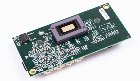
This reference design details the design of a control board for the DLP5531-Q1 DMD. The DLP5531-Q1 DMD is a spatial light modulator with over 1.3 million pixels that can steer light to create digitally controlled illumination distributions. The design shows a simplified power architecture with a reduced component count to save space and reduce cost


Features
- OpenLDI video input
- Reverse voltage and overvoltage protection
- Brownout detection with safe DMD parking
- SPI port for host communication
- I 2C port for diagnostics
- Spread spectrum to support automotive EMI requirements like CISPR 25
- LED enable signals to synchronize LED illumination with the DMD
- CISPR 25 tested design
Applications
- High-resolution ADB headlight and high-resolution symbol projection
- Small light dynamic ground projection
 System Description
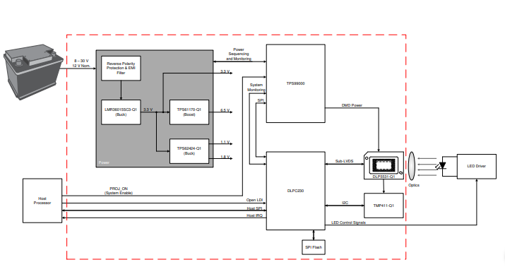
This system is designed to show how the DLP5531-Q1 DMD, in conjunction with the DLPC230-Q1 DMD controller and TPS99000-Q1 system controller, can be used to modulate incoming light from a variety of sources including LED and laser illumination. This design uses a wide VIN buck controller to regulate the incoming battery voltage to an intermediate 3.3V voltage rail that supports the 6.5 V, 1.8 V, and 1.1 V rails which power the DMD controller and system controller. With this architecture the system can operate over a wide range of voltage conditions including cranking and jump start conditions. The system features OpenLDI input for video control over the DMD mirrors. The DLPC230-Q1 generates illumination control signals that synchronize the illumination to the state of the mirrors. There is a SPI port for command and control from the host processor as well as an I2C port that can be used to read a hardware diagnostic register.
This design, in conjunction with a host processor, video source, and illumination source, can be used to create next-generation high-resolution headlights with individual control of over 1.3 million pixels. This best in class resolution can be used to support applications such as high resolution adaptive driving beam (ADB headlight), symbol projection for vehicle-to-environment communication, and unique welcome lighting distributions that allow customers or OEMs to personalize the end vehicle.
High resolution is important for adaptive driving beam applications because it allows much finer control over the light distribution. With ADB headlights, you want to be able to turn off a portion of the light distribution to prevent glare to oncoming drivers. With higher resolution, you can turn off a smaller area, thereby keeping more illumination on the road where you want it. High resolution also allows you to smoothly move the turned off areas of the light distribution with much less jitter which can potentially be distracting to drivers.
High resolution is also critical for symbol projection applications. For a symbol to be readable and therefore useful to the driver or to pedestrians or other vehicles, there must be enough resolution. In a typical application, most of the field of view of a headlight is going to be dedicated to the primary headlight function and only a small portion to the symbol projection function. With 1.3 million pixels, even if you’re only using a small portion of the field of view, you can still create a high-quality symbol.
System Overview
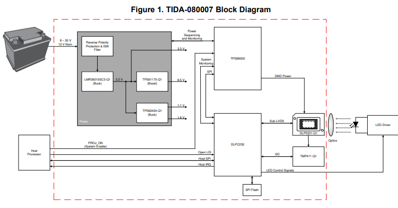
Block Diagram
2.2 Design Considerations
Form Factor
The PCB is designed to match the form factor of the DLP5531-Q1 EVM. This is designed so that these electronics can mate with other optical reference designs.
Power Supply Design
The DLP5531-Q1 chipset requires multiple voltage rails. System voltages that support the TPS99000-Q1, DLPC230-Q1, and DLP5531-Q1 logic are provided by discrete regulators (1.1 V, 1.8 V, 3.3 V, and 6.5 V).
The DMD has specific reset voltages that control the mirror position. These are VRESET (-10 V), VOFFSET (8.5 V), and VBIAS (16 V). Due to the strict tolerances and timing requirements they are provided by the TPS99000-Q1 which was specifically designed for powering the DMD.
The DLP5531-Q1 DMD has strict power up and power down timing requirements. Typically the system is powered up and powered down based on the PROJ_ON signal being asserted by the host processor. However in the case that power loss occurs through and event such as battery being disconnected the system still needs to park the DMD mirrors and remove power in the correct sequence. This series of events is handled by the TPS99000-Q1. The TPS99000-Q1 continuously monitors the system voltage. Should the system voltage drop below a predefined level the TPS99000-Q1 will instruct the DLPC230 to exit display mode, park the DMD mirrors, and disable the DMD voltages in the correct order. The timing for this sequence of events is provided in the TPS99000-Q1 data sheet. Enough capacitance must be available to hold up the voltage rail in the case of a loss of system power. Holdup capacitance can be calculated using Equation 1. A voltage divider on the system voltage monitoring (Vmain) pin of the TPS99000-Q1 sets the trip voltage to begin shutting down the system at 5.4 V. The LM36015 has a typical dropout voltage of 0.4 V. Assuming worst case power consumption values for the DLPC230-Q1, TPS99000-Q1, and DLP5531-Q1 and a required holdup time of 0.9ms we can calculate the required capacitance as shown in Equation 2.
Highlighted Products
DLP5531-Q1 0.55-inch 1.3 Megapixel DMD for Automotive Exterior Lighting
- Qualified for Automotive Applications
- –40°C to 105°C operating DMD array temperature range
- 55-inch diagonal micromirror array
- Bottom illumination for optimal efficiency and optical engine size
- 3-megapixel array configured in 2:1 aspect ratio enabling high resolution and wide aspect ratio automotive applications
- Compatible with LED or laser illumination
- 600-MHz sub-LVDS DMD interface for low power and emission
- 10-kHz DMD refresh rate over temperature extremes
- Built-in self test of DMD memory cells
The DLP5531-Q1 Automotive DMD, combined with the DLPC230-Q1 DMD controller and TPS99000-Q1 system management and illumination controller, provides the capability to achieve high-performance high-resolution headlight systems. The 2:1 aspect ratio supports very wide aspect ratio designs, and the 1.3megapixel resolution enables high resolution symbol projection and adaptive driving beam applications. The DLP5531-Q1 has more than 3 times the optical throughput of the preceding DLP3030-Q1 Automotive DMD enabling an even larger field of view and higher lumen output. The DLP5531-Q1 Automotive DMD micromirror array is configured for bottom illumination which enables highly efficient and more compact optical engine designs. The S450 package has low thermal resistance to the DMD array to enable more efficient thermal solutions.
DLPC230-Q1 Automotive DMD Controller for the DLP553x-Q1 Chipset
- AEC-Q100 qualified with the following results:
- Device temperature grade 2: –40°C to 105°C ambient operating temperature
- Device HBM ESD classification level 2
- Device CDM ESD classification level C4B
- DMD display controller supporting the DLP5531-Q1 automotive exterior lighting chipset
- Video processing
- scales input image to match DMD resolution
- Support for pixel doubling or quadrupling to allow low resolution video input – gamma correction
- Embedded processor with error correction ( ECC )
- On-chip diagnostic and self-test capability
- System diagnostics including temperature monitoring and device interface monitoring
The DLPC230-Q1 integrates an embedded processor with error code correction (SECDED ECC), enabling host control and real-time feedback, on-chip diagnostics, and system monitoring functions. On-chip SRAM is included to remove the need for external DRAM. Sub-LVDS 600-MHz DMD interface allows high DMD refresh rates to generate seamless and brilliant digital images and smooth illumination profiles, while simultaneously reducing radiated emissions.
TPS99000-Q1 System Management and Illumination Controller
- AEC-Q100 qualified with the following results
- Temperature grade 2: –40°C to 105°C ambient operating temperature
- Device HBM ESD classification level 2
- Device CDM ESD classification level C4B
- Automotive system management device for DLP products:
- Advanced power monitoring, sequencing, and protection circuits
- Two die temperature monitors, MCU external watchdog timer, clock frequency monitor
- SPI port with parity, checksum, and password register protection
- Second SPI port for independent system monitoring
- On-chip DMD mirror voltage regulators
- Generates +16-V, +8.5-V and –10-V DMD control voltages
The TPS99000-Q1 system management and illumination controller is part of the DLP5531-Q1 chipset, which also includes the DLPC230-Q1 DMD display controller. An integrated DMD high-voltage regulator supplies DMD mirror reference voltages, meeting the required tight tolerances. The power supply sequencer and monitor provide robust coordination of power-up and power-down events for the entire chipset. The TPS99000-Q1 illumination controller integrates a 12-bit ADC. The ADC is capable of automatic sampling up to 63 events per video frame. Advanced system status monitoring circuits provide real-time visibility into display sub-system operational condition, including two processor watchdog circuits, two die temperature monitors, comprehensive supply monitoring for overvoltage and undervoltage detection, checksum and password register protection with byte-level parity on SPI bus transactions, and other built-in test functions.
System Design Theory
The chipset consists of three components—the DLP5531-Q1 automotive DMD, the DLPC230-Q1, and the TPS99000-Q1. The DMD is a light modulator consisting of tiny mirrors that are used to form and project images. The DLPC230-Q1 is a controller for the DMD; it formats incoming video and controls the timing of the DMD illumination sources and the DMD in order to display the incoming video. The TPS99000-Q1 is a high performance voltage regulator for the DMD and a management IC for the entire chipset. In conjunction, the DLPC230-Q1 and the TPS99000-Q1 can be used for system-level monitoring, diagnostics, and failure detection features.
Components Overview
The TID-080007 DLP Products Headlight Reference Design uses the DLPC230-Q1, TPS99000-Q1, and the DLP5531-Q1 automotive DMD to enable a headlight projection system with unprecedented resolution and grayscale light control. The chipset manages the illumination control of LED sources, power sequencing functions, and system management functions. The chipset supports numerous system diagnostic and built-in self-test (BIST) features.
The DLP5531-Q1 DMD is a micro-electro-mechanical system (MEMS) device that receives electrical signals as an input (video data), and produces a mechanical output (mirror position). The electrical interface to the DMD is a sub-LVDS interface with the DLPC230-Q1. The mechanical output is the state of more than 1.3 million mirrors in the DMD array. Each mirror can be tilted ±12°. By controlling the state of the mirrors designers are able to digitally control the light distribution of a headlight.
The DLPC230-Q1 is a controller for the DMD and the light sources in the DLP headlight module. It receives input video from the host and synchronizes DMD and light source timing in order to achieve the desired light distribution on the road. Since the DMD can only display binary patterns the DLPC230 must process incoming video data and convert it to the native DMD format. The DLPC230 then synchronizes the data displayed on the DMD with light source timing in order to create a video with grayscale shading. The DLPC230-Q1 sends drive enable signals to the LED or laser driver. The control signals to the DMD are sent using a sub-LVDS interface. The sub-LVDS interface is continuously monitored via a high speed training routine that is used to optimize the interface timing as well as detect potential errors on the interface.
Control commands from the host can be sent to the DLPC230-Q1 via I2C or SPI. The bus that is not being used for host commands can be used as a read-only bus for diagnostic purposes. In this design, the SPI bus is used for the command interface and the I2C bus is used for reading diagnostic memory. Input video can be sent over an OpenLDI bus or a 24-bit parallel bus. The 24-bit bus can be limited to only 8bits of data for single light source systems such as headlights. For external video input this design uses the OpenLDI bus.
The SPI flash memory attached to the DLPC230-Q1 stores the default system settings and embedded software for the DLPC230-Q1’s ARM core. The SPI flash memory can be written via the DLPC230-Q1 bootloader application which is stored in the DLPC230-Q1 ROM.
The TMP411 uses an I2C interface to provide the DMD array temperature to the DLPC230-Q1. The outputs of the DLPC230-Q1 are configuration and monitoring commands to the TPS99000-Q1, timing controls to the LED or laser driver, control and data signals to the DMD, and monitoring and diagnostics information to the host processor.
The TPS99000-Q1 provides diagnostic and monitoring information to the DLPC230-Q1 using an SPI bus and several other control signals such as PARKZ, INTZ, and RESETZ to manage power-up and powerdown sequencing. The TPS99000-Q1 is a highly integrated mixed-signal IC that controls DMD power and provides monitoring and diagnostics information for the DLP headlight module. The DLPC230-Q1 communicates with the TPS99000-Q1 over an SPI bus. It uses this to configure the TPS99000-Q1 and to read monitoring and diagnostics information from the TPS99000-Q1.
The power sequencing and monitoring blocks of the TPS99000-Q1 properly power up the DMD and provide accurate DMD voltage rails (–16 V, 8.5 V, and 10 V), and then monitor the system’s power rails during operation. The integration of these functions into one IC significantly reduces design time and complexity versus using a discrete solution. The TPS99000-Q1 receives inputs from the DLPC230-Q1, the power rails it monitors, and the host processor. The DLPC230-Q1’s clocks are also monitored by the watchdogs in the TPS99000-Q1 to detect errors in the DLPC230-Q1 hardware or the embedded software. The power rails are monitored by the TPS99000-Q1 in order to detect power failures or glitches and request a proper power down and parking of the DMD mirrors in case of an error. The host processor can read diagnostics information from the TPS99000-Q1 using a dedicated SPI bus, which enables independent monitoring. Additionally the host can request the image to be turned on or off using a PROJ_ON signal. Lastly, the TPS99000-Q1 has several general-purpose ADCs that can be used to implement system level monitoring functions. The outputs of the TPS99000-Q1 are diagnostic information and error alerts to the DLPC230-Q1. In case of critical system errors, such as power loss, it outputs signals to the DLPC230-Q1 that trigger power down or reset sequences.
Hardware, Software, Testing Requirements, and Test Results
Required Hardware and Software
Hardware
To test the functionality of the TIDA-080007 board simply connect the board to a 12V 1A power supply via J1. Additional features can be tested by connecting an OpenLDI video source to J6. This PCB is designed to drive enable signals to an LED source such as the LED driver found in the DLP5531-Q1 EVM. See the DLP5531-Q1 Electronics Evaluation Module User’s Guide for additional details. TIDA-080007 is also mechanically identical to the DLP5531-Q1 EVM and so is compatible with any optical reference designs that are designed for that EVM.
Software
To get started with the TIDA-080007 hardware, the flash must be programmed using the following steps:
- Connect a Cheetah SPI adapter (Cheetah SPI Host Adapter) to J2 and connect the SPI adapter to a PC running MS Windows 7 or higher.
- Connect a power supply to J1 to power on the device.
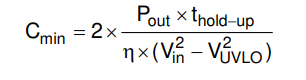
- Connect to the TIDA-080007 board using the DLPC230 Control Program.
- Click the Connect The green circle should then light up to indicate that connection was successful to the Cheetah Adapter.
- To connect, set the DLPC230-Q1 “Host” to SPI and select the Cheetah device from the drop-down menu.
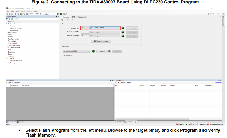
Figure 3. Programming the TIDA-080007 Flash Memory Using the DLPC230 Control Program
Testing and Results
System Test Setup
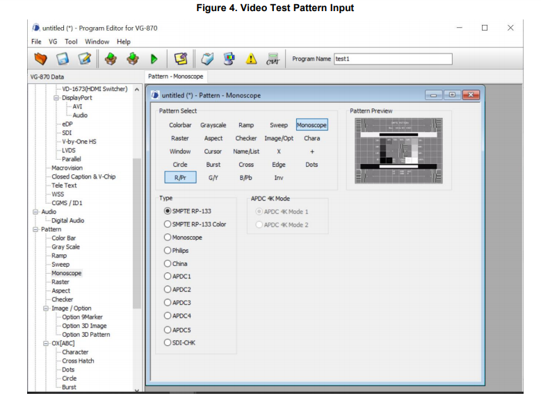
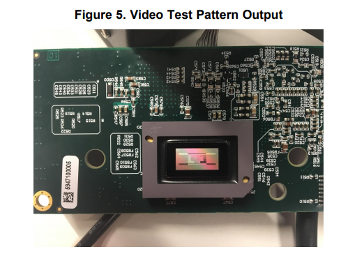
In order to test the device power was supplied by a 12 V lab power supply, Video input over OpenLDI (LVDS) was provided by an Astro VG-870B video generator. Communication over SPI was provided by a Cheetah USB to SPI adapter in conjunction with the DLPC230 Control Program.
System Test Results
Video display
To test the input, an Astro VG-870 with LVDS card was used to output an 1152 x 576 image at 60 Hz. During the test, an image was displayed correctly on the DMD and no system errors were reported.
Shutdown on power loss
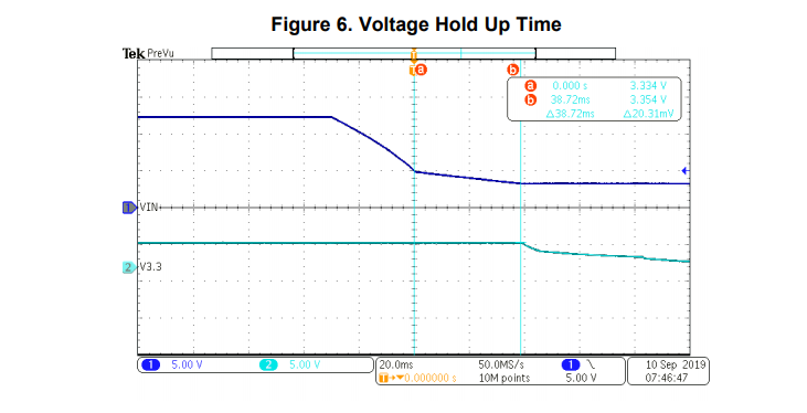
To assure reliable operation, the DMD must properly power down and park the mirrors during a brownout condition. The system must have enough hold up capacitance to power the DLPC230-Q1, TPS99000-Q1, and DLP5531-Q1 until the park procedure is complete. The park timing is described in the TPS99000 data sheet. Power loss detection is tripped when the voltage on the VMAIN monitor of the TPS99000 falls below 1.35 volts. There is a four times voltage divider on the VMAIN pin so the shutdown signal happens at 5.4 V. The system was tested at nominal conditions of 12 V input voltage and 25C ambient operating temperature. Figure 6 shows the hold up time from when the input voltage monitor trips to when the 3.3 V regulator stops regulating. This exceeds the data sheet timing requirement.
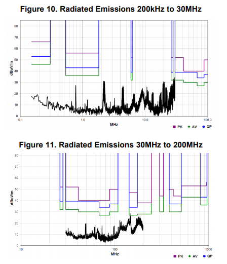
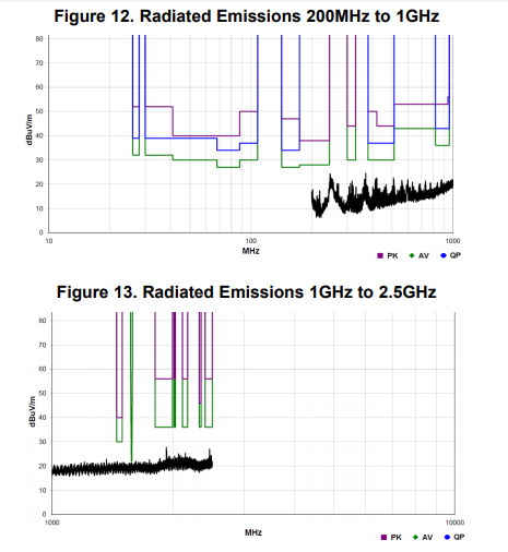
EMC Test Setup
Limited EMC pre-compliance testing was done at a third-party accredited lab. Testing was performed while displaying video test patterns from the DLPC230 internal pattern generator with spread spectrum enabled. This design showed acceptable results, meeting the requirements for CISPR 25 Class 5 in some cases, CISPR 25 Class 3 radiated emissions in most cases and CISPR 25 Class 1 radiated emissions overall. It is recommenced that pre-compliance testing begins at an early stage in the design process especially if targeting more stringent CISPR 25 Class 5 or OEM specific EMC requirements. Results from the EMC testing are provided below. All graphs are shown with the CISPR 25 Class 3 limits. Only the graphs are shown in this report. Tables may be provided upon request.
Figure 7 shows the test setup using a biconical antenna for the 30MHz to 200MHz range.
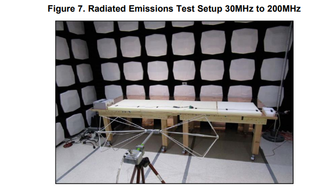
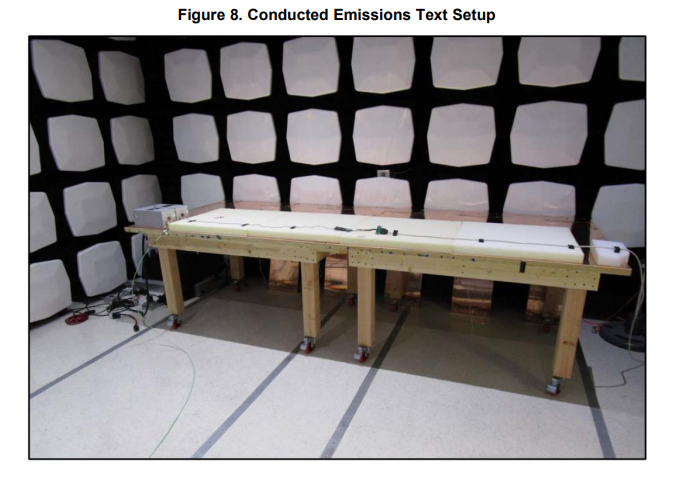
Figure 8 shows the test setup for conducted emissions with the LISNs (line impedance stabilization network) connections shown on the left side, they are the grey boxes.
EMC Test Results
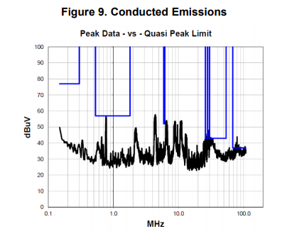
Conducted Emissions
In Figure 9, emissions from 150kHz to approximately 26MHz meet CISPR 25 Class 3 conducted emissions. At approximately 26MHz emissions meet Class 1 conducted emissions. At approximately 80MHz, emissions meet Class 1 conducted emissions. Only the measurement from the positive lead is shown as it is nearly identical to the return (ground) lead.
Radiated Emissions
From 200kHz to 30MHz, emissions meet CISPR 25 Class 3 limits. From 30MHz to 200MHz, emissions meet CISPR 25 Class 3 limits except for at approximately 145MHz where emissions still meet CISPR 25 Class 1 limits. Beyond 200MHz, emissions meet CISPR 25 Class 5 limits.