


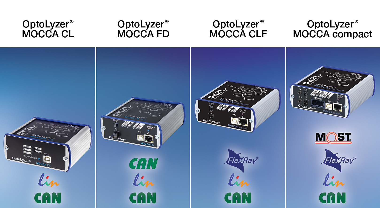
The OptoLyzer MOCCA Family is K2L’s product line of automotive bus interfaces. Reaching from the OptoLyzer MOCCA CL featuring six standard CAN and six LIN interfaces to the OptoLyzer MOCCA compact devices with six standard CAN, six LIN, one FlexRay and one MOST interface, the OptoLyzer MOCCA Family offers tailor-made solutions for different usage scenarios. The devices can be used for application tests, stimulation and verification as well as for gateway applications. Together with K2L’s OptoLyzer Studio software, the OptoLyzer MOCCA Family devices are of indispensable help during the entire development process. In this article we focus on the OptoLyzer MOCCA FD, a development tool for CAN FD, CAN and LIN. Besides the hardware, we will discuss the software options that are available for users of the OptoLyzer MOCCA FD – OptoLyzer Studio and K2L.Bus.
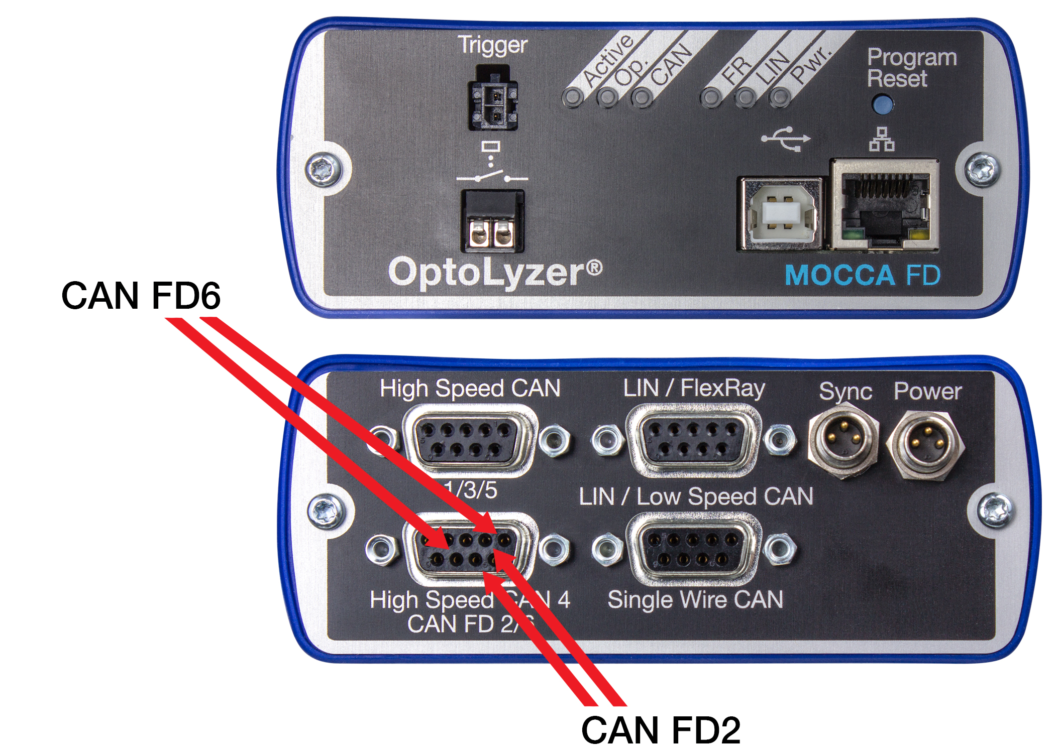
Interfaces of the OptoLyzer MOCCA FD


The OptoLyzer MOCCA FD is equipped with two CAN-FD interfaces that can also be configured as CAN High-Speed, CAN Low-Speed or Single Wire CAN. Additionally, it comes with si LIN interfaces and four standard CAN interfaces. In terms of CAN-FD, ISO and non-ISO CRC calculation is supported. The accuracy of the CAN FD time stamps is below one microsecond. Additionally, the MOCCA FD has a trigger interface as well as a relay in place. For the connection to the PC the device is equipped with a USB 2.0 interface.
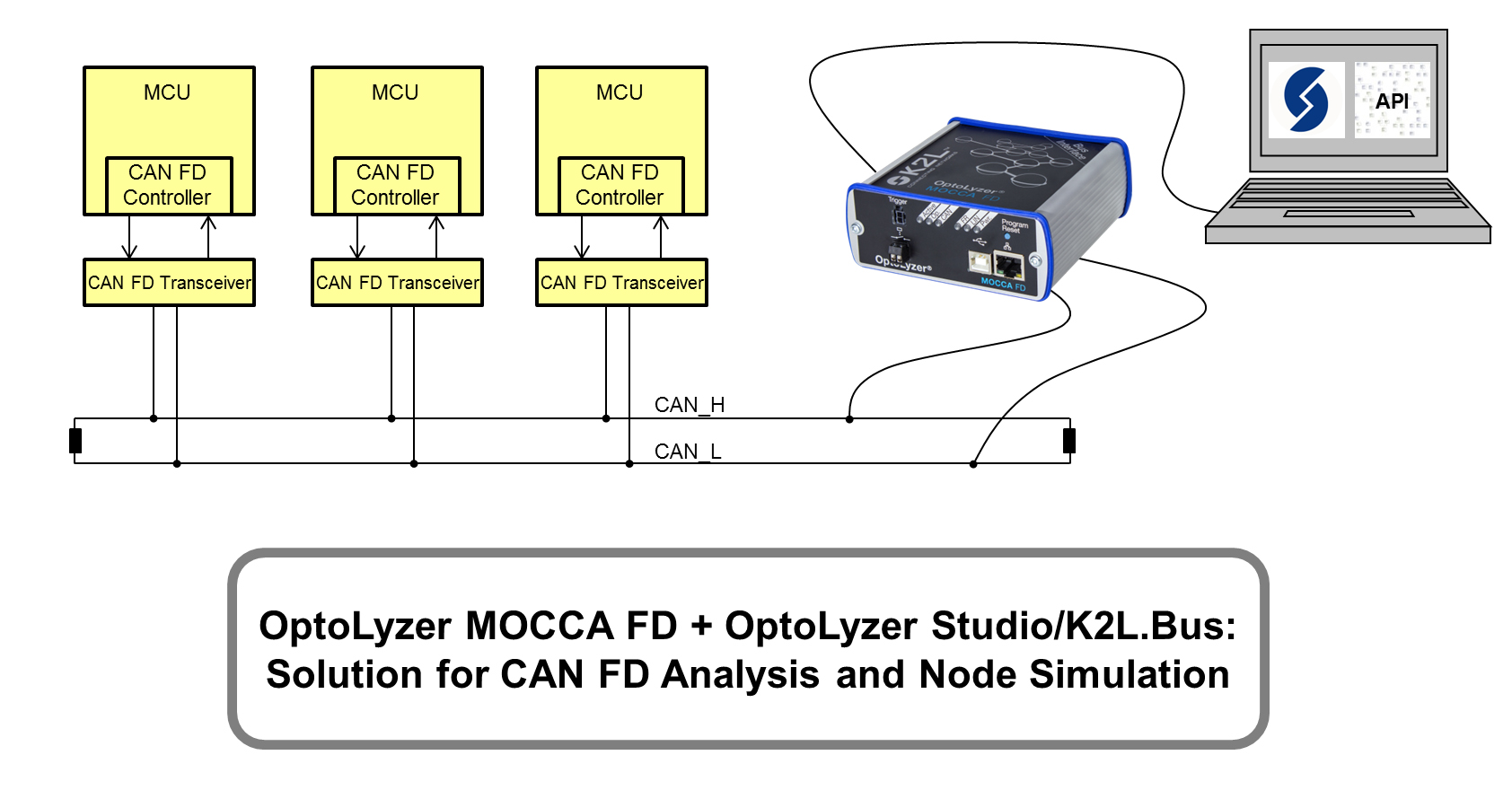
OptoLyzer MOCCA FD Use Cases
With the OptoLyzer MOCCA FD two main use cases during the development can be covered. As Picture 3 indicates, the first use case of the OptoLyzer MOCCA FD is to trace and to analyze activities on the bus. The MOCCA FD interfaces directly to the CAN FD bus. On the other side it is connected via USB to the notebook that is running K2L’s development software – OptoLyzer Studio or the programming API K2L. Bus that comes with the OptoLyzer MOCCA FD. The second use case goes beyond pure analysis. Here, a CAN FD node is replaced or simulated by an OptoLyzer MOCCA FD and OptoLyzer Studio and a custom application based on K2L Bus respectively. In the system depicted in Picture 3, the combination of OptoLyzer MOCCA FD and PC software would constitute a fourth CAN FD node in the network.
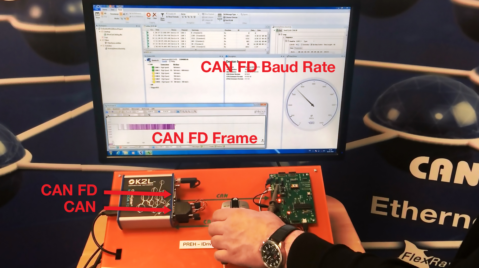
As an example of the latter use case, the screenshot in Picture 4 depicts a small CAN FD demo system. In the foreground an OptoLyzer MOCCA FD that is connected via CAN to a Preh
IDriveand via CAN FD to a CAN FD evaluation board from Microchip. The OptoLyzer MOCCA FD is connected additionally via USB to a PC that is running OptoLyzer Studio. This can be seen from the computer screen in the background. The smaller window on the PC is from a Pico Technology oscilloscope that is attached to the Microchip evaluation board. It shows the CAN FD frames that are transmitted over the CAN FD bus. The OptoLyzer Studio shows the baud rate of the CAN FD data phase with the help of a tachometer plugin window. In this demo system, the transmission speed of the data phase of the CAN FD communication can be changed with the help of the IDrive.
OptoLyzer MOCCA FD Software Options – OptoLyzer Studio and K2L.Bus
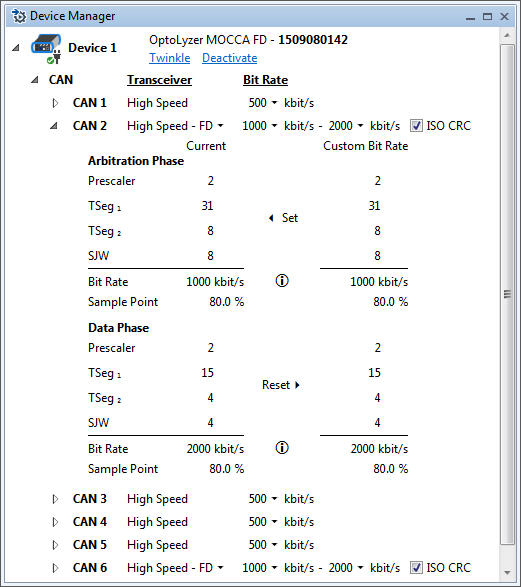
The network interfaces of the OptoLyzer MOCCA FD hardware can be configured by using K2L’s powerful OptoLyzer Studio software. Apart from the modification of standard settings such as baud rate and bit timing (see Picture 5), the software provides highly sophisticated features: The Trace View neatly displays the traffic on the attached busses, signal behaviour can be observed in a Graph View during online measurements and in offline mode. Additionally, the Filter Editor can be used to define filter conditions. Stimulation of bus interfaces is straight forward with the help of the Activity View.
The free-of-charge K2L.Bus API provides customer programmable access to the OptoLyzer MOCCA FD K2L Bus is a NET dynamic link library developed with C# which can be employed during the development of actual NET test and simulation application. A set of examples is available that show how to access OptoLyzer MOCCA hardware interfaces from within custom C# programs (http://k2l.de/Downloads/OptoLyzerStudioExamples.zip).
More Information
OptoLyzer MOCCA Family webpage on K2L website
CAN FD Analysis and Simulation with OptoLyzer® MOCCA FD video on youtube