This article elucidates reference designs of the Three-Phase Smart Energy Meter developed by STMicroelectronics and the advantages of shunts over current sensors for poly-phase metrology.
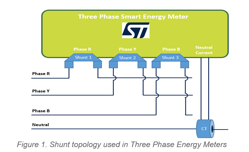


Nowadays, people are becoming more concerned about monitoring and controlling power consumption, be it heavy machinery or home appliances. As shown in figure 1, Shunt based metering solutions, in combination with new STMicroelectronics advanced galvanic isolation technology presents several advantages over the traditional current transformer (CT) current sensing method:
- Lower cost, especially for high current applications.
- With isolation, a shunt can be used for each phase.
- Modular solution for several metrology architectures.
- Guaranteed immunity to noise due to short analog tracks from the transducer to metrology Analog front-end (AFE).
- 6kV data isolation.
- Protection from electromagnetic tampers.
- Robustness against Electromagnetic Interference (EMI)
- STMicroelectronics provides reliable solutions for metering, compliant with the latest available standards (EN 50470-x, IEC 62053-2x, ANSI12.2x) for AC watt meters.
Why current transformers (CT) are used in energy meters?
CTs are used extensively in the metering industry for measuring Alternating Current (AC). It has a ferromagnetic core, a primary and a secondary winding of copper wire.
The phase or neutral wire on which the current to be measured is passed through the CT ring. The AC in the phase wire (primary) produces an alternating magnetic field in the core which then induces an AC in the secondary winding of the CT. The number of turns in primary and secondary windings are chosen to scale the primary current to a measurable value. A burden resistor connected across the secondary winding produces an output voltage based on the amount of current flowing through it.
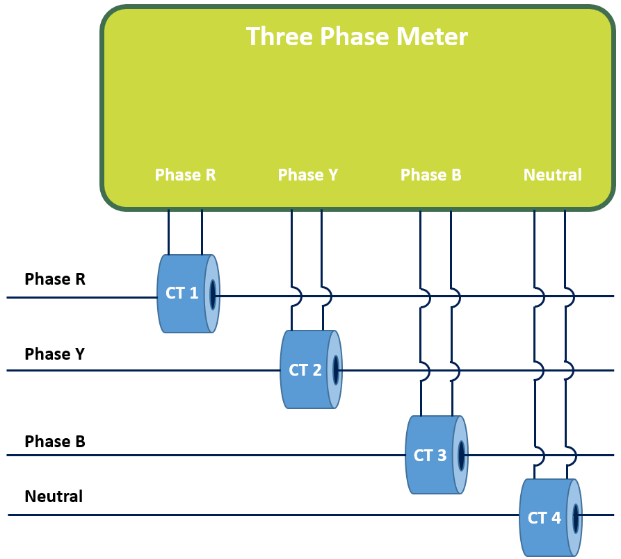
Figure 2 is showcasing a CT-based traditional Energy Meter. Some advantages that make CT universal in the metering design are:
- Higher sensitivity compared to other sensing methods.
- Low power dissipation
- Inherent isolation from the Mains
Therefore, the main reason behind using CT is safety from high voltage hazards.
Limitations of CT
- CT’s ferromagnetic core saturates beyond a rated input current. Therefore, it does not have a linear response as the output current is no more proportional to the input current.
- Accurate linearity for high current values requires more expensive sensors which further increases the cost.
- A strong magnet near the meter can saturate the CT which distorts the flux in the core. As a result, high input current produces only a small output variation which tampers the actual reading of the meter and the electricity bill.
- CT introduces a phase shift in the output current which can lead to large errors in power and energy measurement.
- Harmonic distortions cause EMI disturbances in the input signal of CT.
Due to the above reasons, it is worth considering topologies using shunt for three-phase meters.
Advantages of Shunt over CT
- CT cannot measure DC because there is no change in flux for DC. Whereas Shunt can measure both as it is a resistor with very little resistance in the order of milliohms (10-3).
- The accuracy of a shunt is much better that is why most precision Multimeters use it for current measurement. A Shunt is also able to measure low currents in the order of micro-ohms (10-6).
- The cost of a shunt is much lower as compared to CT, especially for the high current range, due to its inherent linearity.
- The footprint of a shunt is also very small, so housed in few millimeters while CT has huge footprints.
- A shunt is independent of magnetic fields in the surroundings, hence magnetic tampering does not affect shunt-based meters.
- Moreover, a shunt does not introduce any phase shift or change in the current like CT, thus eliminating the need for phase compensation.
Shunt Variants
Shunts can be used for many applications like shunt diode, circuit protection, and current measurement. For current measurement, there are few variants of shunts that are used.
- 2-terminal shunt: It is a traditional shunt having a resistive element between two copper frame terminals.
- 4-terminal shunt: It has two terminals on either side of the resistive measurement element and the other two terminals are at the end of the copper frame. Terminals on the copper frame are used to connect cables driving current, while the internal terminals, close to the resistive element, are connected to the AFE device for voltage measurement across them. Since the resistive element has controlled resistivity and lower temperature drift which results in more accuracy.
- 5-terminal shunt: It is similar to a 4-terminal shunt. In addition, a fifth terminal is present on one side of the copper frame, close to the resistive measurement element. It is used as a ground reference for current measurement which gives higher stability and increases noise rejection.
For the designs mentioned below, a five terminal shunt is used to measure the current being drawn. It is a 3W and 0.3 mΩ resistor. A preamplification gain of 16x on the current channel, selectable for both the metrology devices (STPMS2 and STPM32/STPM33) assures a current range up to 100A. The voltage across the shunt resistor, proportional to the input current, is sensed by the ADCs of these devices.
The STPM3x is an Application Specific Standard Product (ASSP) family designed for high accuracy measurement of power and energies in power line systems.
The STPMS2, a two-channel 24-bit second-order sigma-delta modulator, can measure voltage and current for each phase. It then oversamples the signals using a synchronized 4MHz clock and multiplexes voltage and current sigma-delta bitstreams on a single output pin.
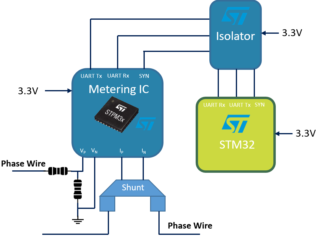
In shunt-based solutions, it is mandatory to isolate the phases from each other’s, because the potential difference on the Printed Circuit Board (PCB), due to the direct contact with the line wire, can be in the range of hundreds of volts. This can produce a discharge current that would destroy the board and the equipment connected to it. Isolation is achieved using the STISO621, a dual-channel digital isolator based on ST’s 6kV thick-oxide galvanic-isolation technology to transfer data between isolated domains in a variety of industrial applications.
As we can see in figure 3, an isolator is used between the microcontroller and STPM32 or STPMS2 metering device.
STPM32 based Three-Phase Smart Energy Meter
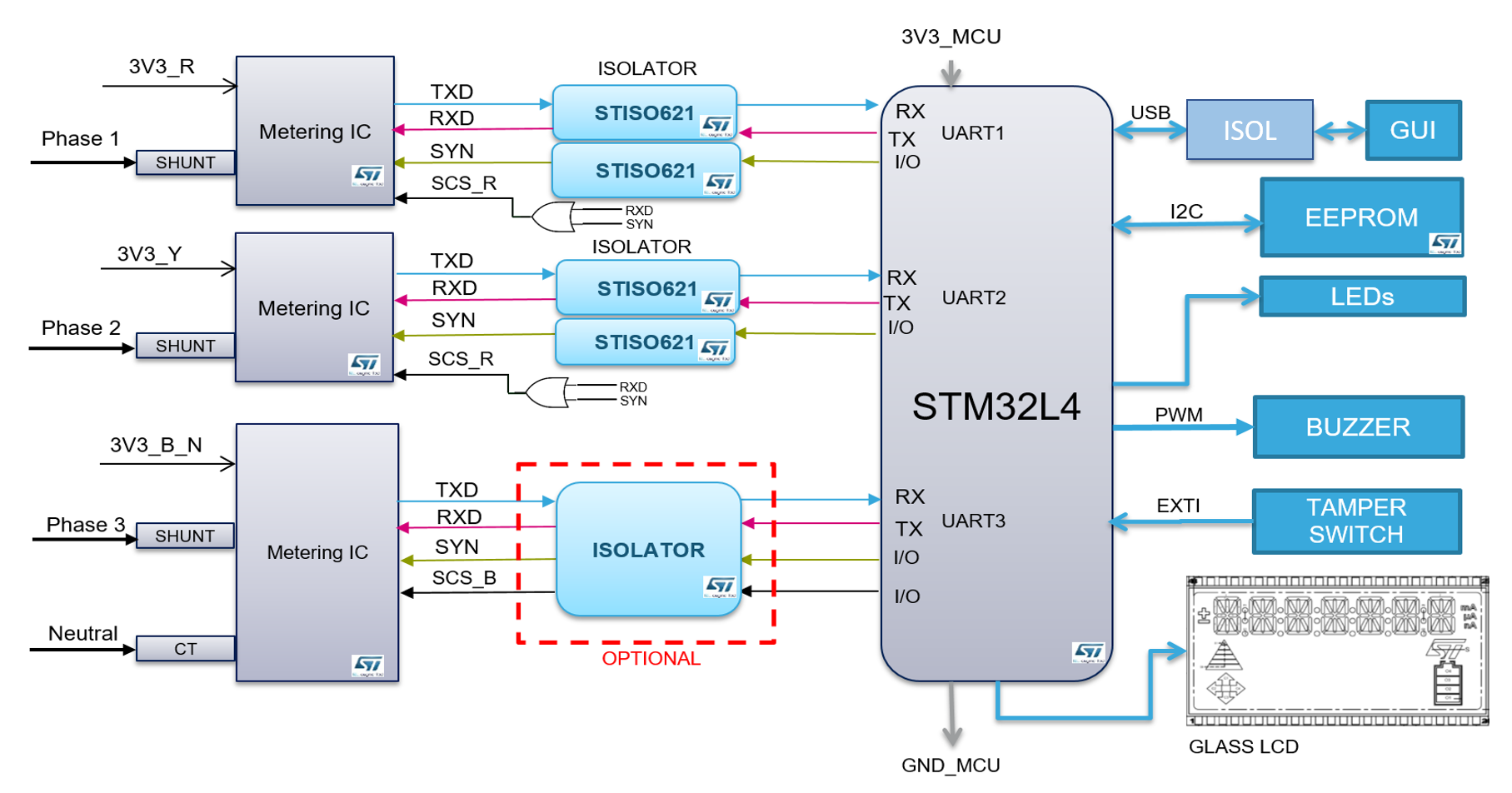
Consumers who want to control their electricity bills and the industries where precise power, energy, and power factor of heavy machinery must be monitored, this meter (as shown in figure 4) provides a way to sense and control the power and energy consumption. It calculates all the metrology parameters essential for measuring every milliwatt of power consumed by the industry or household. STPM32 metering IC and STM32L486 microcontroller are used for this design.
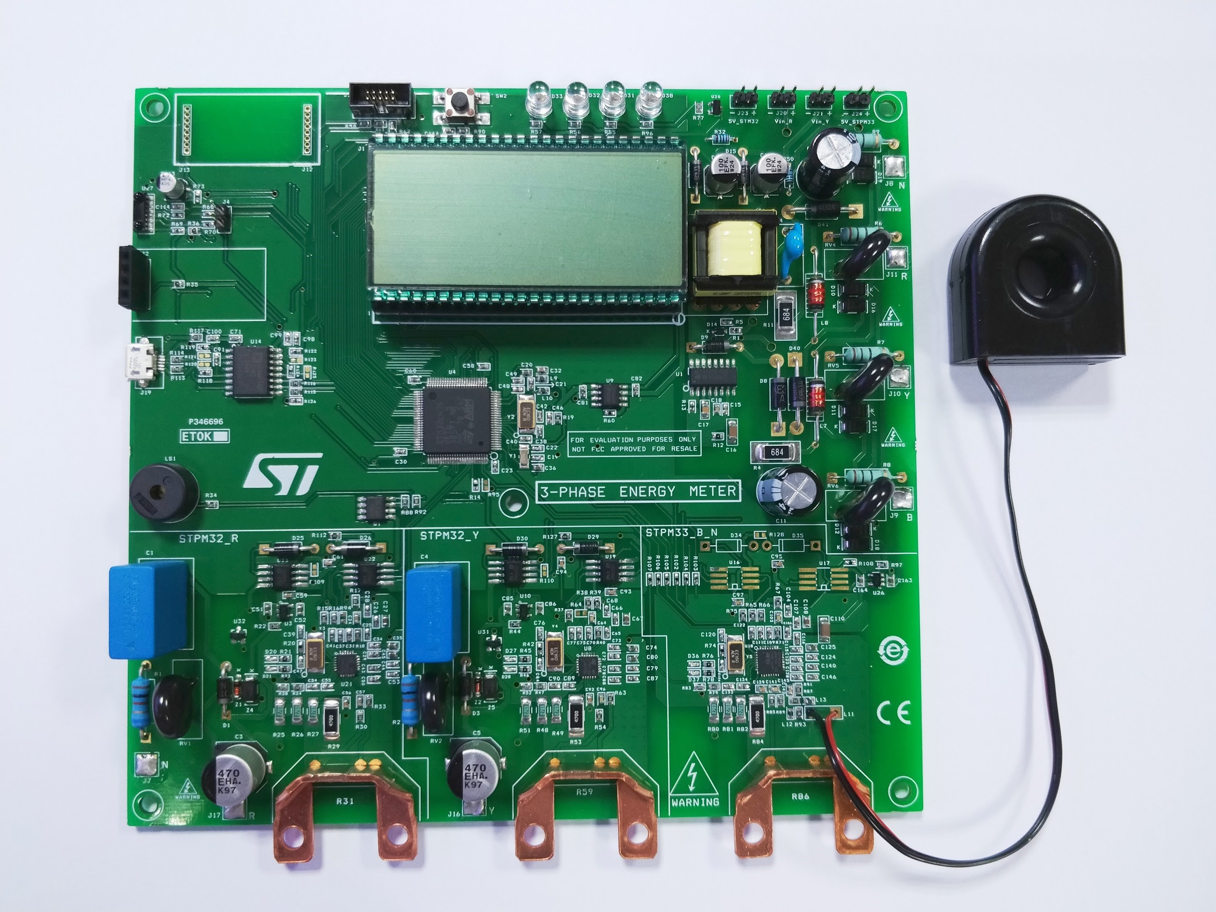
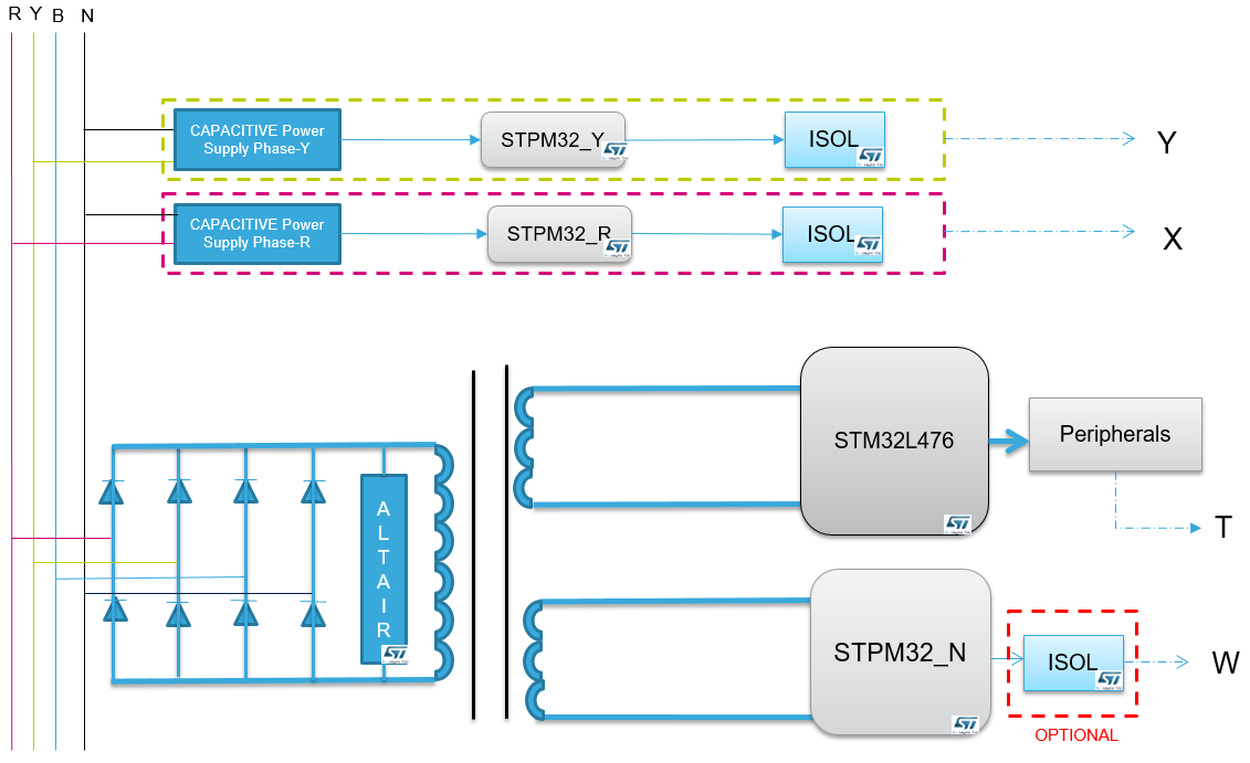
Figure 5 & Figure 6 are explaining the block diagram of the design.
STPMS2 based Three-Phase Energy Meter (EVALST-3PHISO)
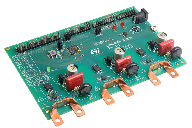
EVALSTPM-3PHISO (as shown in figure 7) evaluation board implements a complete three-phase energy meter with shunt current sensors. The solution is based on the STPMS2 device, a double channel, 24-bits second-order sigma-delta modulator. Sensing circuitry and PCB layout are optimized to maximize the signal-to-noise ratio for optimal accuracy.
The STPMS2 oversamples the signal using a 4 MHz clock distributed in a synchronized way by the microcontroller and outputs voltage and current sigma-delta bitstreams, multiplexed on the same pin.
The two-wire communication between STPMS2 modulator and MCU is isolated by STISO621W, a 6 kV galvanic isolated interface, allowing up to 100 Mbps rate and low pulse distortion (<3ns) for safe and fast data transfer between isolated domains.
The firmware embedded in the solution exploits the DFSDM filters of the STM32F413RH to convert the six bitstreams into 24-bits voltage and current data, at a 200us rate. It also implements a Virtual COM Port communication to easily access the internal parameters to read metrology data, to modify the internal configuration for high flexibility of the application, and to calibrate the board.
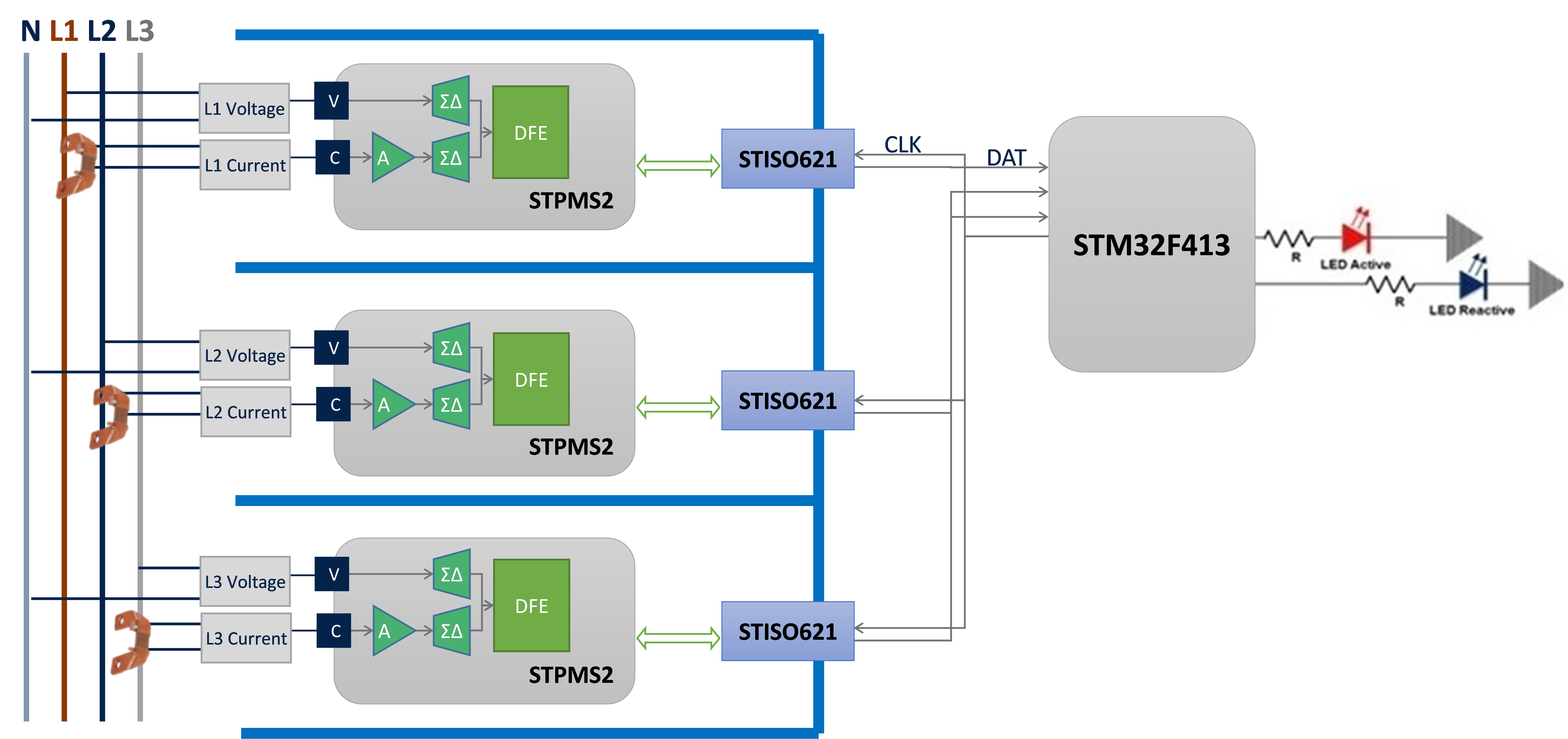
Figure 8 is the block diagram of EVALSTPM-3PHISO. The documentation, tools, and resources for this design are available at https://www.st.com/en/evaluation-tools/evalstpm-3phiso.html
Conclusion
Given the increasing interest in shunt current sensing for the metering industry, ST proposes a reliable and accurate solution for the measurement and control of energy in the domestic and industrial environment, showing how to use the shunt for current sensing. It assures complete immunity to DC and AC magnetic fields and current sensing without any phase shift while lowering the overall system cost. The small form factor ensures a compact circuit board, with very few components to assemble. Of course, it is not only limited to energy metering. Solar inverters, process monitoring, and protective devices can all get benefit from Shunt topology.
Authors: