


By Mangesh Kale, Narayani Ghatwai, Suresh Repudi (eInfochips)
Introduction


Embedded software designs such as those for avionics and automotive systems have become highly complex to develop, test and certify. As a result, the traditional document driven environments, without coordination among involved developers, are quality and costs associated with the lifecycle of such embedded software programs. In this context, model-based design (MBD) processes when used effectively, provide a unified design environment so that developers can use a single set of models for their entire lifecycle for requirements validation, data analysis, model visualization, testing and validation, and ultimately product deployment, with or without automatic code generation. Model-based design is a framework for virtual prototyping of embedded software. MBD has evolved to overcome the difficulties and complexities that typically occur during the design lifecycle of embedded software for closed- loop control systems or DSP applications. Such software needs to be designed in an iterative manner with extensive involvement of multi-disciplinary teams. In most of the practical scenarios, such embedded software design needs to start (as well as tested) before physical prototypes and systems are available. With traditional design processes, the discovery of errors in design and requirements are found late in the design cycle, which may result in expensive delays. MBD framework targets to address such issues early in the design phase and it can significantly minimize the rework in later phase of the life cycle.
A crucial step in model based development process is verification and validation of code on embedded CPU or DSP. This step enables detection of flaws in the procedures that involve algorithm design to C code conversion, and enables pre-emptive measures to mitigate the issues related code compilation, binary code optimizations as well as CPU/DSP architecture specific limitations. Most of such design issues, if not identified, can pass undetected through functional performance testing carried out typically within offline simulation environment such as Simulink.
Background:
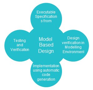
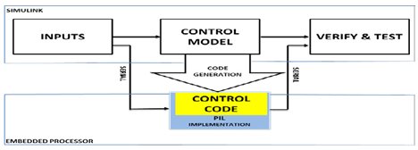
As embedded software becomes more complicated, the activities of design, verification, validation and testing becomes even more complex to examine and justify. The model based development process adapts use of graphical models as a way to accord with the increased intricacy. Such model-based development is also linked to simulation, graphical models of product capability to enhance verification and validation processes as shown in the Figure1.
Model based development and testing:
In MBD environment, the design team develop models to analyze and formulate high level, as well as the meticulous low-level requirements. Such models can have the primary architecture for the solution, but are usually independent on the embedded target platform. Such design models implement major requirements that can be proved in exact manner in the simulation and to illustrate the deducible top–level requirements, often specified as an executable specification.
The sharing of model artefacts and efforts between the design and testing teams allows for further confirmation of embedded code to hardware specific requirements, and enables a more concentrated testing of the code and fixing of errors in a lesser time. The verification, validation and associated testing activities are typically implemented at every stage within model based design process. Test mechanisms (tasks) that verify, validate, and test the model and software include:
- Model-in-Loop (MIL) to evaluate the algorithms in the simulation environment at initial stages of the development cycle
- Software-in-Loop (SIL) to justify the conduct of the generated software code used in the controller
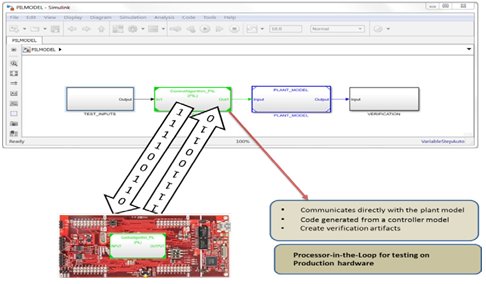
- Processor-in-Loop (PIL) provides a framework to verify the actual controller code on a dedicated microcontroller or DSP that interacts with a simulation in the software environment
- Hardware-in-Loop (HIL) for real-time testing involving actual system components
Model design and testing:
The foremost of the integration level is based on the model of the system itself. Testing an embedded system design on the MIL (model-in-Loop testing) level means that the model and its environment are simulated (interpreted) in the modelling framework without any physical hardware components.
This allows testing at the initial stage of the development cycle. It also validates the requirements used as the initial point of the development process. Information gathered through the simulation becomes the benchmark for code verification.
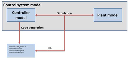
In this case, the model is adapted further according to the end goals of the embedded platform. The controller model is coded in C or C++ (can be auto-generate code) and then inserted back into the simulation environment to evaluate it along with the plant simulation.
This type of validation is especially useful for the software components consisting of a combination of generated code and handwritten code that need to be integrated and executed on the embedded target platform. The SIL tests typically reuse the data and model structures from MIL for examining the code behavior in simulation. Generally, the embedded software and the simulated environment model run on the same machine.
Processor-in-loop testing:
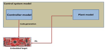
This step incorporates changes to the controller code for embedded hardware features that allows execution and tuning on the target microcontroller or DSP. The PIL setup involves loading the compiled object code onto the target processor or DSP and then run the simulations on the plant model for verification. This is a non-real time setup and hence allows execution of a large number of V&V test suits to evaluate embedded CPU/DSP capability to run controller algorithms. If there are differences between SIL and PIL results, then PIL object code is fine-tuned (for example) for fixed-point precision, memory footprint or compiler optimization flags and so on.
Hardware-in-loop testing:
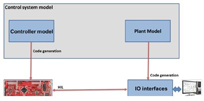
After the controller code has been verified using PIL, the next step usually involves substituting the plant model with the actual system (or a lab prototype) or a real-time simulator running the plant model. For example, if a DC motor speed controller is being designed then the controller code is deployed on the microcontroller or DSP board that is then interfaced to a real DC motor by connecting the inputs and outputs at the interface points such as sensors and power electronics components.
HIL testing is one of the last integration levels that allows debugging and evaluation of functional and operational tests in a manageable way in a real-time environment. Often a substantial amount of software based test automation and logging, as well as hardware interfacing components, are required to implement a reliable HIL setup. The PIL setup is comparatively easier and requires less hardware and software resources.
PIL implementation considerations:
The main purpose of PIL is to bridge the gap between controller model design performed in simulation software and the actual controller code executing on the target (figure 5). The PIL approach as shown in figure 5 can identify the errors that may originate in the compiler. The PIL environment also allows debugging the algorithm functionality and evaluation of the numerical performance of embedded microcontroller or DSP. Furthermore, the PIL setup can offer important measurements of the software system such as memory usage and execution time. Such data can be used to fine tune controller functions in a simulation environment and embedded hardware design relatively early at the beginning of the design process.
Microcontroller or DSP Performance:
The performance of an embedded CPU (a key component of the controller hardware) usually depends on the following factors:
- Processor speed or clock rate
- Computational delay, Interrupt latencies
- Floating point performance or Fixed point capability
- SRAM or onboard Flash memory
- On-board peripherals such as ADC, DAC, PWM, bus interfaces
In addition to above factors, it is important to note that control algorithms cannot be executed without certain in-evitable delays caused by ADC, DAC, de-nosing filters, de-bouncing logic and anti-aliasing filters. There is a finite time delay between the beginning of a sample interval, i.e. the activation of ISR (interrupt service routine), reading of sensors and the final update of the actuators. These all factors lead to time latencies, and in some cases synchronization issues when a large number of sensor and actuation channels exist within the system.
These latencies and computational delays depend on the processor architecture as well as the complexity of the control algorithms. For example, a 32 bit Arm Cortex M3 will have a much better real-time embedded performance compared to a Cortex A family.
The next most important parameter is cost vs performance ratio of the processor and longevity of the product guaranteed by the manufacturer.
The hardware acceleration features in a processor are useful to speed up tasks with less software involvement. It can enable multiprocessing, that can benefit mixed sample rate systems. The desired performance may be achieved by a processor either with higher processing power or with a slow power efficient processor, accompanied by a set of hardware accelerators (e.g. Control Loop Booster feature in the STM32 family of 32-bit Flash microcontrollers based on the ARM Cortex-M processor and TI ARM Cortex-M4F-based MCUs). Both approaches have their own pros and cons, hence, shall be considered against scaling of the control system requirement.
Therefore, the selection and evaluation of the embedded processor is often a very crucial step and helps to ensure the intended performance of complex control algorithms, as demonstrated in the simulation, is achieved in actual implementation.
Processor-in-Loop data exchange and communication channels:
To establish a communication link within the embedded processor-in-loop simulation setup typically interfaces such as SPI, UART or I2C are used. The simulation environment running on the host computer communicates with the object code executing on the microcontroller or DSP, typically within an evaluation board, as shown in Figure 6.
The simulation tool sends the data values from the plant model to the firmware on the evaluation board through the high-speed serial link and receives the data from the firmware through the same or other communication channel.
Such communication link allows testing in a non-real time such that the embedded platform (with the microcontroller/ DSP) becomes an integrated component or subsystem of the simulation environment allowing controlled debugging, evaluation, logging, and testing.
Processor-in-Loop Case Study at eInfochips
In this project, eInfochips team designed and implemented a Processor-in-loop (PIL) simulation setup for speed control of a three phase BLDC motor within Model Based Design environment. The motor speed is controlled by duty cycle of PWM signal, controlling the H-bridge logic and subsequent commutation. This setup (Figure 7) consists of TI (TMS320F2807) evaluation board, NI8451 (National instruments) board, CCS studio and Matlab/Simulink. Initially, an offline closed-loop simulation setup consisting of a simulation model of BLDC motor, PWM switching and a speed controller is implemented in Simulink. The PID controller is tuned extensively across various load conditions. This is Phase 1 i.e. Model-in-Loop setup. Then in Phase 2, the controller is implemented as C code and then executed in TI MCU while interfaced to motor simulation in Simulink as shown in Figure 7.

Phase 1 (MIL):
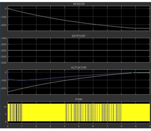
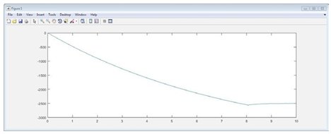
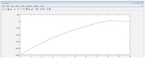
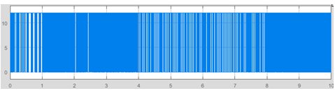
This is model-in-loop simulation consisting of plant (BLDC motor) and the controller as shown in Figure 8. A PID controller continually calculates an error value as the difference between desired speed setpoint and measured motor speed and applies a PWM duty cycle adjustment (1 msec sample rate). The correspondingly plots for sensed speed, controller commands and PWM switching are shown in Figure 9.
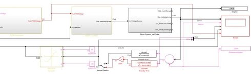
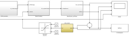
Phase 2 (PIL):
In this PIL setup, motor speed values calculated in Simulink are sent as inputs to the embedded PID algorithm running in the TI MCU. The PIL block in Simulink serves as an interface and passes the plant model inputs to the code running on the embedded microprocessor (TI MCU). Similarly, the outputs of the PID control algorithm are calculated by executing code on the TI MCU (TMS320F2807) and are then fed back into the Simulink plant model via SPI communication (as shown in the Figure 10). Figure 11, 12 and 13 show some typical results from PIL setup and match with Phase 1(MIL) results in Figure9.
References:
- CLARENCE W. de SILVA “Sensors and Actuators Control systems Instrumentation”
- Speed Control of a D.C. motor
- Processor-in-the-loop tutorial
- How in the loop testing aids embedded system validation
About Authors
Dr. Mangesh Kale is the Senior Solution Architect and Key Accounts Manager at eInfochips.
Narayani Ghatwai is an engineer at eInfochips.
Suresh Repudi is the Tech Lead at eInfochips.
For more information, visit www.einfochips.com