


Abstract
With the wide use of energy storage devices such as batteries and supercapacitors, the current trend is to simplify battery charge and discharge management. A bidirectional DC/DC converter can accomplish this to maintain a healthy battery and extend battery runtime. The bidirectional converter uses one powertrain to implement the charge and discharge operation. This paper describes how Renesas Electronics has integrated bidirectional control into its latest controller, the ISL81601, enabling easy implementation of on-the-fly reverse-direction power flow and control.


Introduction
The world and the way we live our daily lives is changing as we reduce our dependence on imported oil and harness renewable energy. Increasing the use of battery-operated portable devices is also playing a major role with our evolving lifestyle. The key element contributing to this trend is the development of energy storage technologies and the wide use of high-density devices such as lithium-ion (Li-ion) batteries and supercapacitors.
These energy storage devices attach to renewable energy systems such as wind power and solar power to collect and store the energy and then supply stable power to the grid or commercial and residential end users. Portable devices such as a cell phone, drone, robot, and even an electric vehicle rely solely on the power from energy storage devices to operate and complete their tasks. Information technology for the fast-growing data economy is the other force driving the rapidly changing world. The importance of keeping information systems such as a data center or a telecom system operating 24 hours a day means they cannot afford to lose power and shut down.
Energy storage devices are needed to back up power for these information systems. An energy storage device collects and stores energy by charging itself from an electrical power source, and then it supplies the stored power to the loads by discharging itself. The charge and discharge process needs to be precisely managed to ensure the safe, reliable, and long life of the storage devices. In most applications, the charge and discharge function is typically controlled by two separate power trains to implement the different control targets such as a smaller charge current vs. a larger discharge current for a Li-ion battery.
However, a fast charge-to-discharge or fast discharge-to-charge transition is needed for some applications. For example, a DC battery backup system used in a data center server needs to implement a fast charge-to-discharge transition to implement a seamless power delivery; whereas, a motor drive system for a braking operation requires a fast discharge-to-charge transition. A single power train on-the-fly bidirectional charge and discharge converter is needed for these applications to achieve a seamless fast transition between charge and discharge operation.
By combining the charge and discharge powertrain together, a compact design can be achieved and the system cost can be reduced, which can also benefit those applications that don’t require a fast charge and discharge transition. The ISL81601 buck-boost controller provides an easy and reliable solution to the on-the-fly bidirectional DC/DC power conversion for the storage device charge and discharge control applications. Its unique architecture and control algorithm give customers the technical confidence and business value they need.
Bidirectional DC/DC Converter Topologies
Bidirectional operation can be implemented in a converter with a synchronous rectifier (SR) for both isolated and non-isolated topologies. This paper only focuses on non-isolated topologies to simplify the discussion. The conclusions can also be extended to an isolated topology by adding an isolation transformer.
Typical non-isolated bidirectional converters are buck, boost, and four-switch buck-boost as shown in Figure 1. It is obvious that a buck converter can run as a boost converter in the reverse direction. And a boost converter can run as a buck converter in the reverse direction. Since the four-switch buck-boost converter runs in either two-switch buck mode or two-switch boost mode, it can also easily work in reverse direction similarly to a single buck or boost converter.
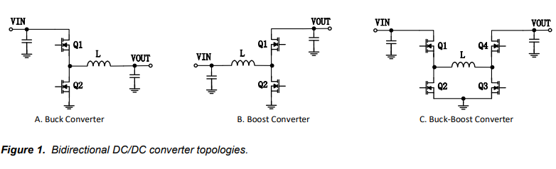
Figure 2 shows two different typical bidirectional operation systems: 2A, battery charge/discharge bidirectional operation system and 2B, supercapacitor backup system. The ISL81601 is a four-switch buck-boost controller capable of implementing on-the-fly bidirectional operation.
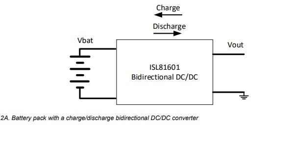
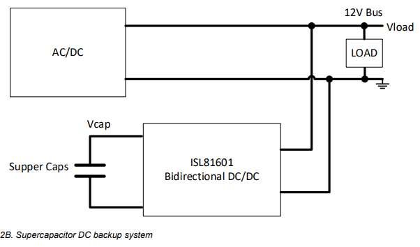
Figure 2. Typical applications of bidirectional DC/DC converter
In a battery charge/discharge system, the bidirectional DC/DC converter can be a four-switch buck-boost converter when Vout is near the battery operation voltage, or it can be a boost converter when Vout is always higher than the battery voltage, or it can be a buck converter when Vout is always lower than the battery voltage. The four-switch buck-boost converter achieves the best efficiency because it uses lower voltage rating power devices and lower operating current. It can also ensure safe battery operation because of its capability to provide the full overcurrent and short circuit protection on both charge and discharge operation.
In a supercapacitor DC back-up system, the bidirectional DC/DC converter should be a buck-boost converter because the capacitor needs to discharge to a very low voltage to fully utilize its capacity.
Four-switch Buck-boost DC/DC Converter Bidirectional Operation
Figure 3 shows the four-switch buck-boost converter operation modes and waveforms controlled by the ISL81601. When Vin is lower than Vout, it runs in boost mode, as shown in Figure 3C. When Vin is higher than Vout, it runs in buck mode, as shown in Figure 3A. When Vin is close to Vout, it runs in buck-boost (one cycle buck followed by one cycle boost) mode as shown in Figure 3B.
Bidirectional operation can be implemented in all three operation modes. The converter keeps the same PWM modulation algorithm for both forward and reverse direction control. The inductor current is positive in forward direction power conversion and negative in reverse direction. Rs_in and Rs_out are used to sense input and output current.
With a proper offset on the current-sense op amps in the controller, the ISL81601 can sense and control both positive and negative currents on both input and output ends. This is important for the reliable operation of a bidirectional DC/DC converter.
In a bidirectional DC/DC converter, controlling the input/output voltage and current is required. The ISL81601 integrates four control loops to regulate Vin, Vout, Iin, and Iout as shown in Figure 4. Gm1 senses Vout and regulates Vout in the forward direction to implement constant voltage (CV) output operation. A2 senses Iout via Rs_out. The average Iout is proportional to the voltage on the IMON_OUT pin. Gm4 regulates the average Iout to implement constant current (CC) output operation in the forward direction. A1 and Gm3 are used to sense and regulate average input current Iin in the forward direction.
Gm2 senses and regulates Vin in reverse-direction operation. The four average control loops are ORed together. The lowest Gm output takes control. The CV CC operation transition and reverse direction transition are then implemented on the fly automatically by the ORed loop control architecture. In the supercapacitor DC backup system shown in Figure 2B, the DC/DC converter input VIN shown in Figure 4 is connected to a 12V bus, and the output VOUT is connected to the supercapacitor pack. In its forward power conversion direction, the converter charges up the supercapacitor when the AC line and 12V bus are available. The capacitor is charged in CC mode, controlled by the A2/Gm4 loop shown in Figure 4 when VOUT is lower than the set point of the Gm1 voltage loop.
When the capacitor VOUT is charged up to the Gm1 voltage loop set point, the VOUT is regulated and maintained at the set point. The converter runs in CV mode to keep the capacitor in a fully charged condition. In the forward direction, the ISL81601 provides pulse-by-pulse peak inductor current limit protection to ensure reliable operation in transient and short-circuit conditions. A second-level peak current protection is also provided to shut down the converter at output dead-short condition.
Design 4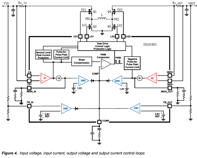
When the AC line loses power as shown in Figure 2B, the AC/DC converter stops supplying power to the 12V bus, and the 12V bus voltage (VIN) is lowered by the loads.
When the VIN drops to below the set point defined by FB_IN=0.8V, Gm2 takes control to pull the COMP pin lower. This reduces the PWM duty cycle, and the inductor current decreases from positive to negative territory. The converter reverses its power conversion direction on the fly to discharge the supercapacitor and supply current to the loads on the 12V bus. The VIN voltage is regulated at its set point.
The on-the-fly reverse direction operation and the buck-boost mode transition are illustrated in the waveforms in Figure 5. To show the operation detail, the VIN initial voltage is set to 18V, VIN Gm3 regulation is set to 9V, and the VOUT Gm1 regulation is set to 12V. When the VIN source is removed (similar to losing the AC line shown in Figure 2B), the caps on the VIN continue to discharge in forward power conversion to charge the supercapacitors. While the VIN drops from 18V to 9V, the converter runs in buck, buck-boost, and boost mode to keep the VOUT in regulation. The ISL81601 internal logic ensures a smooth and automatic transition between buck, boost and buck-boost modes in both directions.
When the VIN drops to 9V, Gm2 loop kicks in to regulate the VIN at 9V. The inductor current transmits to negative territory to reverse the power-conversion direction. The supercapacitors discharge to supply the power to the loads on the VIN. The reverse-direction operation is automatically implemented on the fly. To limit the VIN dip, the Gm2 loop bandwidth should be fast enough to ensure the backup power quickly kicks in. This can be done by adding a capacitor in parallel with the upper resistor of the VIN feedback-resistor divider.
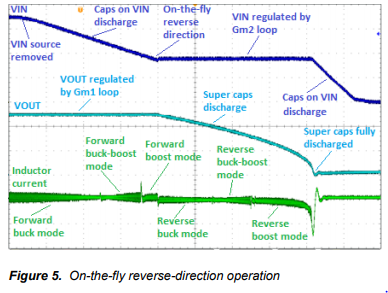
During the reverse-direction operation, the supercapacitors discharge to lower the VOUT. During VOUT descent, the converter runs in reverse buck, buck-boost, and boost mode to maintain the VIN in regulation continuously until the VOUT decreases to near 0V. The stored energy in the supercapacitors is fully utilized.
With the use of ISL81601, the peak negative inductor current can be limited pulse by pulse to ensure the safe reverse-direction operation.
CC/CV Control in a Battery Pack Charge/Discharge Bidirectional Operation System
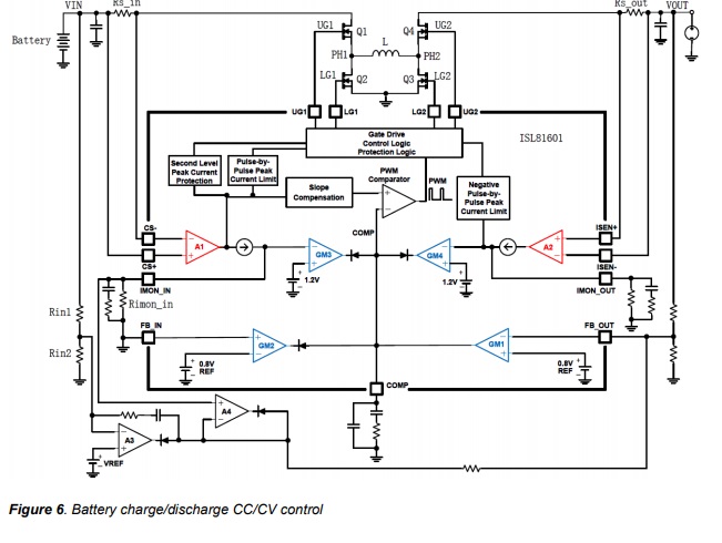
In a battery pack charge/discharge bidirectional DC/DC converter, as shown in Figure 2A, CC/CV control is needed for both directions. Figure 6 shows the battery pack DC/DC converter block diagram. The battery pack is connected to the VIN end of the DC/DC converter. In the forward battery discharge direction, the VOUT CV control is done by Gm1, and the Iout CC control is done by A2 and Gm4.
In the reverse-direction battery charge operation, the CC and CV charge control can also be implemented by adding two op amp A3 and A4 circuitries to the ISL81601 controller; see Figure 6.
To charge the battery, a DC source is applied to the VOUT terminal. When the DC source voltage is higher than the Gm1 loop VOUT regulation set point defined by the 0.8V reference and the resistor divider to FB_OUT pin, the buckboost converter automatically draws current from the DC source to charge the battery in the VIN end. This is implemented by the control loop to reduce the COMP pin voltage and, thus, the PWM duty cycle. The inductor current decreases to negative territory, and the converter reverses the power conversion direction.
With the negative current in Rs_in, the IMON_IN pin voltage drops to lower than its offset point, Vimon_in_offset, defined by EQ.1.
Vimon_in_offset = Ics_offset x Rimon_in EQ.1
Where:
Ics_offset is the offset current of the current sense amplifier A1; typical 20uA shown in the ISL81601 datasheet. Rimon_in is the resistor connected to IMON_IN pin.
As shown in Figure 6, when IMON_IN pin voltage drops below the Gm1 reference voltage of 0.8V, A4 starts to pull FB_OUT lower. The COMP pin voltage increases. Thus, the PWM duty cycle increases. The inductor negative current decreases. The negative battery charge current is regulated to implement the CC charge. The constant charge current set point Icc_in is defined by EQ. 2.
Icc_in = (Ics_offset – 0.8/Rimon_in)/Gm_a1/Rs_in EQ.2
Where:
Gm_a1 is the gain of current sense amplifier A1; typical 200uS shown in the ISL81601 datasheet. Rs_in is the input shunt-sense resistance.
When the battery charges up to the point where the VIN voltage divider Rin1/Rin2 output is higher than VREF, A3 starts to pull FB_OUT lower. Like the CC control, the COMP pin voltage increases. The PWM duty cycle increases. The inductor negative current; i.e., battery charge current, reduces to 0A or to the positive discharge territory. The White Paper — Design Considerations for a Bidirectional DC/DC Converter Page 8 of 9 battery voltage is regulated to implement the constant voltage charge. The constant voltage set point Vcv_in is defined by EQ. 3.
Vcv_in = (Rin1 + Rin2) x VREF/Rin2 EQ.3
When the battery is fully charged, the DC source is removed. The battery pack is ready to power any load in CC or CV mode controlled by Gm4 or Gm1.
In automotive or any other motor drive applications, the ISL81601 bidirectional DC/DC controller automatically implements the instant energy feedback to the battery in motor braking condition on the fly. The peak surge braking current is limited by the ISL81601 pulse-by-pulse peak negative-current limit function implemented by Rs_out and the current sense amplifier A2. The long-term braking current is limited to the constant battery-charge current loop set point Icc_in. The combination of the fast peak and accurate constant current limit and the battery max-charge voltage limit implemented by the battery CV control loop ensure safe system operation.
In Figure 6, FB_IN is grounded to disable the Gm2 function. By feeding the VIN signal to the FB_IN pin via a resistor divider, Gm2 can actually be used in this kind of battery pack application to protect battery over discharge. When the battery is over discharged, Gm2 will lower the COMP pin voltage to stop further battery discharging.
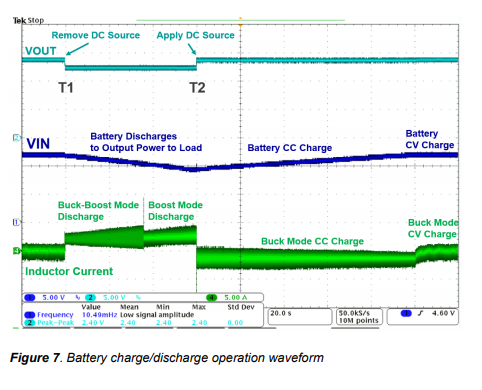
Figure 7 shows the battery charge and discharge operation waveforms. When the DC source is removed at T1, the battery starts to discharge to output the power to the load immediately on the fly. When the DC source is reapplied at T2, the DC/DC converter immediately changes its direction on the fly to charge the battery. The battery is charged in CC mode when the voltage is lower than the VIN regulation set point and CV mode when the voltage reaches the set point.
Conclusions
The Renesas ISL81601 is a highly integrated, comprehensive bidirectional buck-boost PWM controller. The device’s unique system architecture makes it easy to control both voltage and current on output and input ends in forward and reverse directions in a four-switch buck-boost DC/DC converter. This capability provides a simple, reliable on-the-fly bidirectional DC/DC power conversion solution. It also provides a high-degree of flexibility to customers requiring solutions to various applications of energy storage devices.
Source: Renesas Electronics