


Most standard vector network analyzers (VNAs) are instruments with ports mounted in a single chassis. This paradigm is used to keep the source and measurement circuitry close together to simplify designs and enable the very strict synchronization needed for high frequency vector S-parameter measurements. For most benchtop applications, having ports tied to a single chassis is not a significant issue since short high quality coax cabling can be used to interface between the ports and the device under test (DUT) with minimal effect on the quality of the S-parameter measurement.
However, as frequencies climb higher and higher, the effect of cabling on S-parameter measurements starts to become more significant. Standard software techniques have been developed to de-embed the characteristics of the cabling from the measurement so that the test results reflect the performance of the DUT alone. This works reasonably well in the typical bench top application where the setup is reasonably close to the VNA and the RF characteristics of the cables and fixtures stay very stable so that their effect on the measurement from device-to-device can be effectively removed by the de-embedding process.


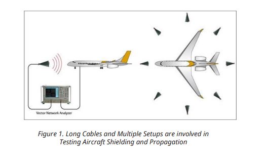
But, not all VNA test setups fit nicely into this stable benchtop use model. Larger DUTs and over-the-air (OTA) testing typically require longer test port cables to connect a typical single chassis VNA to device connectors or test antennas used to make these types of measurements. Most of these applications also require multiple setups which require those interface cables to be moved and repositioned affecting the stability of the measurement. An example of this type of application is RF shielding and propagation testing of larger vehicles like an airplane (see Figure 1).
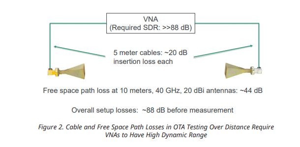
Long cables connecting the VNA ports to the DUT can have several negative effects on S-parameter measurements. At millimeter-wave (mmWave) frequencies a few meters of cable can add significant insertion loss between the DUT and the VNA. A coax cable at 40 GHz can add approximately 4 dB per meter loss to the measurement path. A typical midsize to large OTA chamber with the VNA located outside the chamber can easily require 4 or 5 meters of expensive microwave coax cable to connect the VNA ports to the source antenna and the antenna under test (AUT) in the chamber. Assuming 5 meters of cable is required on each port to reach inside the chamber, the cabling can add 40 dB of additional insertion loss to the measurement path at 40 GHz, significantly reducing the effective dynamic range of the overall system.
For tests like far field antenna characterization, there is generally a large amount of free space path loss due to the distances required between the source and test antennas. That OTA loss combined with the interface cable losses makes the dynamic range required of the VNA for these measurements very challenging (Figure 2). This results in needing to use very expensive high performance VNAs in these types of OTA chamber applications.
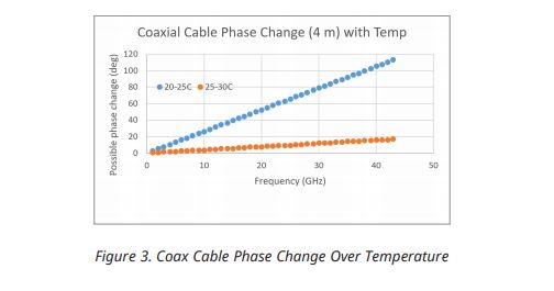
Long cables also introduce instability into the measurement setup. With minor changes in ambient temperature or with moderate movement, coax cables can add several degrees of phase shift to a measurement causing significant deviations. Because these phase deviations are due to environmental conditions that are prone to change and can be difficult or impossible to control, it is very difficult to de-embed the cable affects from the measurement in a reliable fashion.
An example of the possible phase change from a good quality cable is shown in Figure 3. The plot shows the phase change in a four meter coax cable over two 5 degree C temperature ranges. Even at these relatively small temperature ranges the phase change can be significant. For outdoor applications where the cable lengths are typically longer and the temperature swing is larger, this phase change will be even more prevalent.
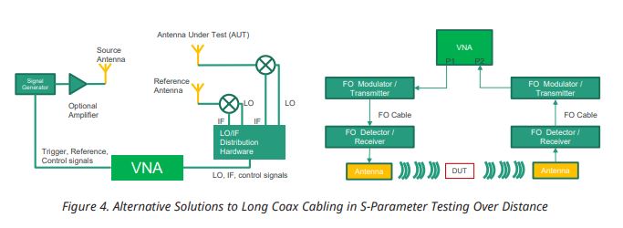
The insertion loss and stability issues with coax cables only become more significant as distances and frequencies increase. The effects are large enough that other methods besides coax cabling must be considered to connect a single chassis VNA to the DUT. Two common methods to replace simple coax cabling in long distance setups are shown in Figure 4. One method uses mixers to down convert test frequencies to lower IF frequencies where coax cables typically have better phase stability and insertion loss characteristics. The other method uses RF over fiber optical transmission techniques to replace coax cables to minimize the high frequency loss and stability issues.
While both alternative methods address many of the negative effects of coax cables on long distance S-parameter measurements, they both add complexity and expense to these types of applications while not addressing the basic issue of having the VNA ports far away from the DUT.
The concept of moving the VNA port closer to the DUT is not new. An example is the use of external multiplier modules for measurement frequencies of approximately 60 GHz and higher where insertion loss and stability issues similar to those described above for longer cable distances become critical issues even for benchtop setups. Practical design and test considerations prompted locating source and measurement circuitry in a mainframe VNA with mmWave circuitry located in multiplier extension modules close to the DUT.
While this multiplier and mainframe architecture effectively allows for moving the VNA port closer to the DUT, the distance from the VNA to the multiplier modules is still limited. The relatively high frequency source and measurement signals that are needed between the extension modules and the VNA still create insertion loss and stability issues that limit the distance that can be supported. To enable more than about a meter of distance between the modules and the VNA, special module and test set designs are needed to deal with the adverse effects of the cables connecting the modules to the VNA.
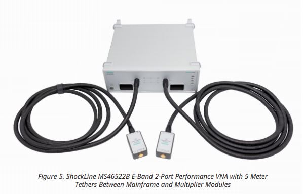
Typical solutions using special cabling and additional amplification have developed to extend distances to approximately 5 meters between the VNA and modules. An example of this is the unique ShockLineTM MS46522B E-band 2-Port Performance VNA with 5 meter tethers (Figure 5) that incorporate the modules, cables, and mainframe into an integrated system. However, as distances grow significantly beyond 5 meters, this mainframe and multiplier architecture becomes impractical.
To simplify long distance high frequency S-parameter testing, a new VNA architecture is required. This new design would need modules that are essentially independent VNAs with complete source and measurement capability that do not rely on signal sourcing or processing back in a mainframe. In addition, phase synchronization between two independent VNAs would be required so that complex 2-port S-parameter measurements could be supported.
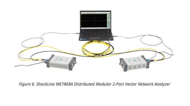
To address this application, Anritsu has introduced the ShockLine ME7868A Distributed 2-Port VNA (Figure 6). Its groundbreaking architecture eliminates the VNA mainframe by using independent ShockLine MS46131A modular 1-Port VNAs with full source and measurement capabilities as portable test ports. Since each 1-port VNA contains a complete source and receiver, insertion loss and measurement stability are improved as high frequency signals are generated and measured local to the DUT eliminating any long distance transmission. With no mainframe connection, the 1-port VNAs are free to be physically distributed over wide distances for independent return loss (RL) measurements.
To enable complex insertion loss (IL) measurements, the two 1-port VNAs must be phase synchronized. Typically, the VNA port synchronization is done in a VNA mainframe, but in the distributed architecture, a new solution is required. To enable the synchronization, Anritsu has developed a groundbreaking technology called PhaseLyncTM that allows the two 1-port VNAs to phase synchronize over large distances of 100 meters or more.
With PhaseLync technology, the 1-port VNAs are able to make synchronized IL measurements with phase stability of ± 2 degrees and magnitude stability well within ± 0.5 dB to 43.5 GHz over a span of several meters between ports. Compare this to the stability of coax cabling over longer distances and the ME7868A distributed 2-Port VNA shows a clear advantage over coax cable.
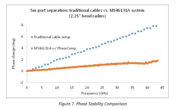
Figure 7 shows a comparison of phase stability of an IL measurement over 5 meters with traditional coax cabling versus the ShockLine ME7868A distributed 2-Port VNA.
The plot shows the phase change over frequency in the two setups. We have a traditional VNA setup measuring an electrically short RF DUT connected with 5 meters of cable bent at a 2.25 inch radius. As you can see, there is approximately six degrees of phase shift at 40 GHz.
Compare that to the ShockLine ME7868A distributed 2-Port VNA with a 5 meter PhaseLync setup. The PhaseLync cable is bent at the same radius measuring the same electrically short DUT. The phase shifts less than 2 degrees at 40 GHz, demonstrating three times better phase stability with PhaseLync than with the coax cable.
With this new architecture, the trend of moving VNA port instrumentation closer to the DUT to simplify S-parameter testing takes a great leap forward. The local generation and measurement of high-frequency signals without the need of a mainframe greatly increases VNA test setup flexibility by eliminating many of the physical constraints of a single chassis architecture. Bringing the VNA port to the DUT also improves dynamic range, stability, and simplifies calibration and fixture de-embedding resulting in better overall s-parameter testing over distance.