


Overview
The growing adoption of electric motors in the automotive industry and in green energy applications has created new challenges for embedded control system developers and test engineers. Electric motor simulation needs to have high fidelity; HIL (hardware-in-the-loop) test systems must be able to execute simulation models on the order of 1 µs to adequately simulate the electric motor behavior. This combination of simulation fidelity and execution speed has previously been impossible; many test engineers had to rely on a more costly dynamometer or field testing to validate their embedded software.
Using the latest technology for real-time high-fidelity electric motor simulation, you can test many types of transient and fault conditions that are difficult or impractical to perform with real systems. These tests can be destructive to physical hardware. However, with this highly accurate simulation of the physical system, you can exercise the controller at corner cases to ensure real-time safety and security.


The National Instruments HIL platform provides the highest fidelity real-time simulation available in an open, extendable platform for test execution. With the NI platform, you can find problems and optimize performance at an earlier stage of the development process, which reduces the amount of field testing for validating embedded software and, as a result, improves development efficiency.
Testing Challenges
Control inputs and outputs for electric drive engine control units (ECUs) must run much faster than those of a power train ECU for an internal combustion engine. The digital switching signals with higher speed, which control the electric motor system, make the traditional approach to HIL test inadequate. Figure 1 shows the rise in relative error of the simulated response to a 2 kHz and 8 kHz pulse-width modulated (PWM) signal as simulation time step increases.
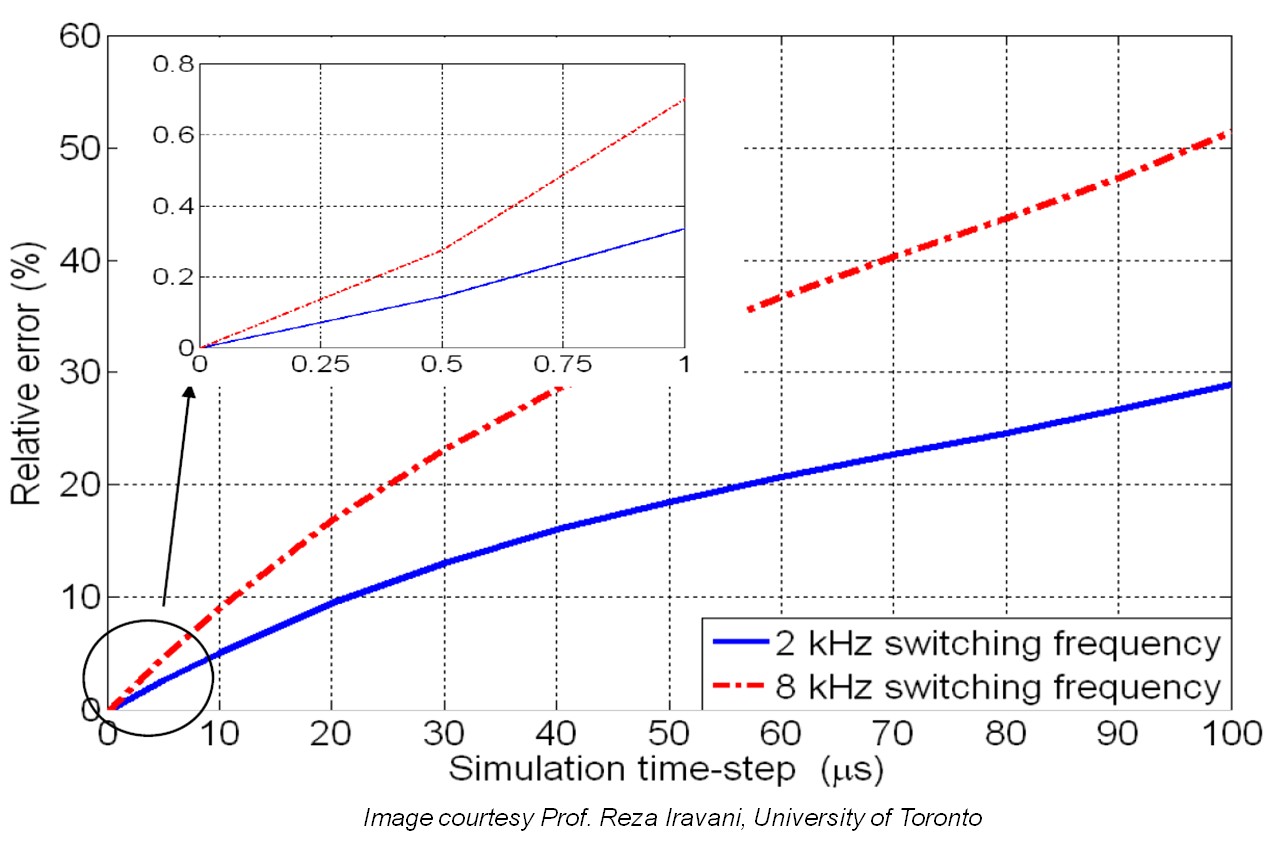
From the graph, you can see that for a simulation loop with a 25 µs period, the simulated response to an 8 kHz PWM has as much as 20% relative error as a result of the time resolution of the simulation. The smaller graph shows an enlarged view of the error in the sub-microsecond range. You can see that the same simulation running at 1 µs has only 0.75% error in the PWM measurement.
To add extra complexity, electric motors exhibit complex non-linear behavior, such as magnetic saturation and cogging torque, which can be difficult to model directly. You can use a linear model to test an ECU for basic functionality, but you also need to model more complex behavior for more stringent testing, tuning and optimization.
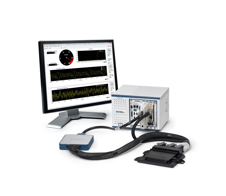
Figure 2 shows three levels of power system testing, including:
- Signal-level testing —simulating the entire system to test the control electronics;
- Power-level testing —using a motor emulator to fully exercise both the control system and the power electronics;
- Mechanical or dynamometer testing
Traditional simulation systems have limited the test capabilities of control system designers and forced them to rely heavily on a costly dynamometer or field testing. However, improving simulation speed and fidelity helps you to do more testing at the signal and power level, reducing the time and cost of the physical testing level.

Approach
Reaching the 1 µs range for simulation periods requires a paradigm shift in the design of electric motor and power electronics HIL test systems. The key technology in simulating systems at such high rates is the shift from traditional processor-based HIL systems to field-programmable gate array (FPGA) based simulators.
Traditional processor-based HIL systems reach maximum speeds of around 50 kHz because a communication bus separates the processor and the I/O. During a single time step of the simulation, the inputs are sampled, that data is transferred to the processor, the result is transferred back to the I/O node, and the outputs are updated. On a PCI or PXI bus, the latency of the communication can typically take up to three-quarters of the overall simulation period. Moving the calculations to an FPGA increases the speed of the calculation itself. However, the biggest boost to speed comes from collocating the processing node and the I/O node on a single device, leading to negligible communication latency.
The next challenge engineers face when conducting a real-time simulation of advanced motor drives is how to attain an adequate combination of simulation fidelity and speed. Whereas a simple constant parameter or linear model can be sufficient to conduct functional-level HIL tests, increased simulation fidelity is often necessary for more robust testing and optimization of advanced motor drives. An effective way to increase the simulation fidelity without adding to the calculation complexity is to replace the model parameters with lookup tables and update those parameters on every simulation iteration.
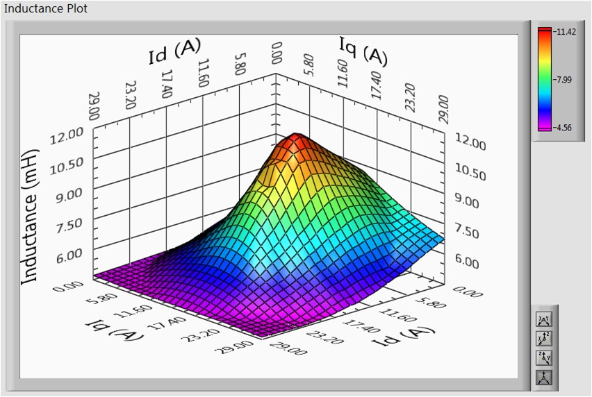
Using finite-element analysis (FEA) results or experimentally derived tables, you can simulate complex non-linear behavior, such as cogging torque or magnetic saturation, and design a controller responding appropriately to the complex phenomena. In each of these cases the lookup table captures the complex behavior without modeling it directly in the simulation. Figure 3 shows an example where the motor inductance varies from 4.5 mH to 12 mH over its operating range.
Solution
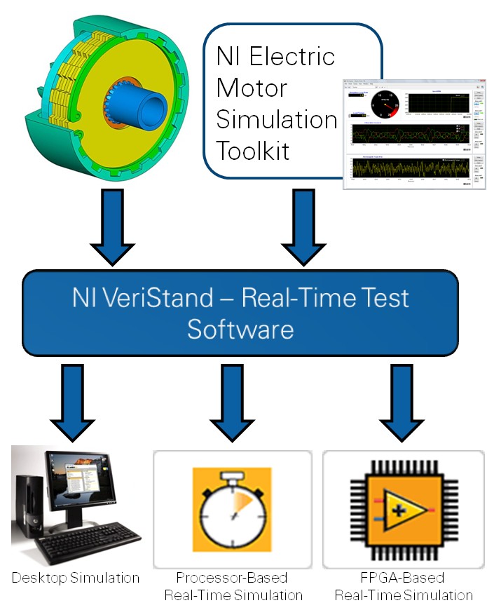
National Instruments has combined hardware and software tools to provide an industry-leading platform for power electronics and electric motor real-time tests. The NI Electric Motor Simulation Toolkit contains models of electrical machines and inverters for control engineers to quickly set up test systems that tie into the greater ecosystem of NI tools for the real-time test.
NI Electric Motor Simulation Toolkit
The NI Electric Motor Simulation Toolkit provides the modeling elements to develop both desktop and HIL simulations of electric motor systems. The toolkit adds a LabVIEW project template for electric motor simulation, control, and HIL simulation. The toolkit also includes VeriStand add-ons for various motor types. You can execute the models on a host computer for software-only simulation, on NI Real-Time targets for traditional HIL simulation, or on NI FPGA targets for high-speed HIL simulation.
The toolkit contains models of Switched Reluctance (SR) and Permanent Magnet Synchronous Machine (PMSM) motor types in a simple linear approximation or in a high-fidelity representation that integrates with JSOL’s JMAG-RT models. The interface with the finite-element analysis (FEA) based JMAG-RT models provides the ability to accurately simulate highly non-linear behavior, such as cogging torque and magnetic saturation.
Following are the supported motor types:
- Permanent Magnet Synchronous Machine (PMSM)
- Constant parameter model
- JMAG-RT FEA-based model
- Switched Reluctance Motors (SRM)
- Linear model
- JMAG-RT FEA-based model
Partnership with JSOL Corporation for HIL Using JMAG-RT Models
National Instruments has partnered with JSOL Corporation to use its FEA tools, JMAG, and JMAG-RT, to generate high-fidelity models that you can use with NI LabVIEW system design software and NI VeriStand software for configuring real-time testing applications. With this partnership, NI is addressing key requirements for electric motor testing and simulation. Now you can run FEA-based motor models with microsecond timing by using LabVIEW FPGA and NI RIO FPGA-based hardware. The models use FEA generated lookup table to parameterize the models in real-time based on the current state of the motor. This combination of linear math and non-linear lookup table provides a very fast and accurate simulation.
NI VeriStand
NI VeriStand is a configuration-based software environment for creating real-time testing applications. It helps you perform real-time target-to-host communication, data logging, stimulus generation, and alarm detection and response. NI VeriStand also transits quickly from simulation-only testing to HIL testing, which helps you reuse test components, such as test profiles, alarms, procedures, and analysis routines. You can remap parameters from models to hardware channels to facilitate real-world I/O. This transition saves you time when performing regression testing and helps you automate tests using test executive software such as NI TestStand.
NI VeriStand features an open framework that you can use to create application-specific functionality through real-time plug-ins. This provides maximum flexibility in your test system. The NI Electric Motor Simulation Toolkit adds motor modeling features to the configuration-based environment so that engineers can perform desktop and real-time simulation and test on a traditional real-time hardware platform, and high-speed simulation on an FPGA.
LabVIEW FPGA
FPGAs are reprogrammable silicon chips. In contrast to processors that you find in your PC, programming on an FPGA rewires the chip itself to implement your functionality rather than run a software application. Ross Freeman, the cofounder of Xilinx, invented the first FPGA in 1985. NI partners with Xilinx to offer their cutting-edge FPGA technology in a variety of hardware platforms and uses LabVIEW FPGA to do graphical programming and floating-point math.
Courtesy: National Instruments