


From an optional lighting system to an essential part in automotive design, from bulbs to LEDs: Automotive rear light systems have come a long way in 100 years, and they will play an even bigger role in the automated driving world.
There were very few and slow cars in the early automotive era from the end of the 1890s until the end of the 1910s: Only front lights were present, as in standard horse drawn carriages. Tail light systems were not mandatory, rear fog and stoplights simply did not exist, and drivers indicated a turn using hand signals.


Driving at higher speeds and night driving resulted in the need to provide a more reliable way to communicate the driver’s intentions. The change from candles to kerosene lamps and the introduction of lights on the rear of the car was imminent.
As wire harness architecture was available in the 1950s, electric lights and proper tail lighting systems became parts of standard car equipment. At the same time, signal lights indicating stops, turns, slowing down, and reverse began to appear. CHMSL (Center High Mounted Stop Light), established in the 1980s, is the latest major new function in rear lighting.
Rear lighting systems were one of the very first human-car interaction system: Their main function is not to directly improve the driver’s experience, but to effectively communicate and interact with other road users in a clear and unambiguous way in order to reduce accidents.
From bulbs to LEDs
LEDs can be considered a major technological change in any lighting application. LEDs increase system efficiency and reliability. Changes in the automotive illumination system are drastic: from one or two bulbs to multiple LEDs per function, from standard round housing to any linear shapes. Furthermore, light animation features are now available.
In addition, rear lighting systems turned from purely functional communication systems into an important part of a carmaker’s design language. Resulting from reduced LED dimensions, new lighting effects and visuals are now in use.
A good example is the animated turn light. This feature has a limited impact in communication efficiency and does not directly affect the driver’s experience. However, it is a very effective style choice that impresses other road users. New dynamic and decorative light functions such as welcome or logo animation are also introduced.
LED matrices in rear light systems are able to show additional information such as the words ‘STOP’ or ‘SLOW’ when braking or in coasting mode. In this case, however, harmonization amongst carmakers and countries’ regulation is still necessary as this feature is in contrast with the worldwide standard conventions and could create confusion or slow down the reaction of other drivers who need time to read and interpret the message.
Signal wire transmission architecture – current status and limits
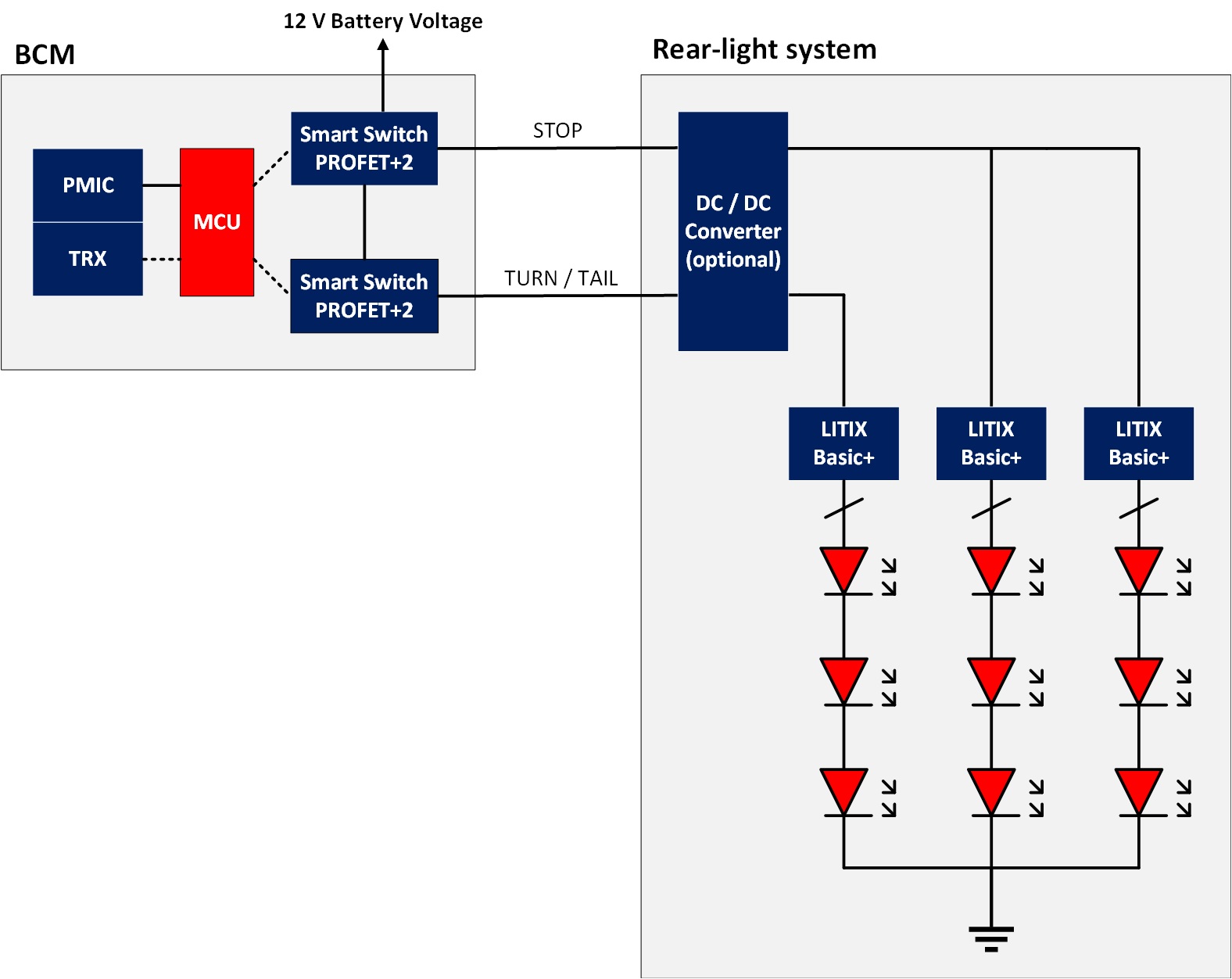
The first standard rear light architecture was based on signal wire transmission coming from the Body Control Module (BCM), that acts as the main intelligent master. In this setup, the microcontroller (MCU) is located in the BCM, a Power Management Integrated Circuit (PMIC) and a transceiver (TRX) supply the MCU and communicate with other modules.
In this architecture, one signal wire corresponds to one light function – in some cases, the power supply and the signal wire are the same – and is electrically protected by a smart high-side switch (see Fig. 1), such as an Infineon PROFET +2 device. The only available features are switching the lights on or off and digital dimming to switch between tail and stop functions.
This architecture has not changed much since the introduction of bulbs and it is still very popular today, as it fulfills all basic functions for a rear light system: to communicate the driver’s intentions and to indicate vehicle presence even across a long distance in a very simple and effective way.
Each string is driven by LED drivers such as Infineon’s LITIX Basic+ devices to control load current with a high accuracy and enable analog/digital dimming as well as diagnostic/protection functions. If some basic animation is required, additional wires are necessary from the BCM to the rear light module for every LED string. (Fig. 1)
Thermal management challenge
Thermal management is one of the biggest challenges in this first architecture: LED lifetime and performance are strongly impacted by temperature. Moreover, LED drivers such as LITIX Basic+ are linear circuits and their power dissipation PDR(max) is linearly dependent on the battery voltage.
LED efficiency usually decreases with higher junction temperature, so a higher current may be necessary to ensure the same lamp brightness. This could lead to a positive feedback loop between current and temperature, which must be avoided.
Equation 1 and 2 help to better understand the relationship among driver junction temperature TJDR, LED current ILED(max) and LED drivers ambient temperature TAMB(max): designer should ensure that actual thermal resistance value Rth(JA) is lower than the maximum allowed Rth(JA)(max).
Equation 1:
PDR(max) = ∆VDR x ILED(max), where ∆VDR = VBATT(max) – VLED
Equation 2:
TJDR = TAMB(max) + (PDR(max) x Rth(JA)) è Rth(JA)(max) = (TJDR – TAMB(max))/PDR(max) Eq. 2
An example for corner case is:
VBATT(max) = 16 V
ILED(max) = 60 mA per channel
VLED = 2 V per LED, 3 LEDs per string
TAMB(max) = 75°C, TJDR = 150°C
Which leads to these figures:
PDR(max) = (16 V – 6 V) x 180 mA = 1.8 W
Rth(JA)(max) = (150°C – 75°C) / 1.8 W ≈ 42 K/W
New animation trends require that automotive rear lights appear as pure surface instead of dots, so light diffusion through optical solutions is adopted: the main drawback is the reduction of LED brightness efficiency, so a higher current or more LEDs are now needed.
If a higher LED current is imposed an even lower maximum thermal resistance value for the same driver is required, thus leading to an increased effort in the thermal system design. Common solutions are larger PCB area or thicker copper layers. However, this has negative impact on system costs when many LED drivers are required or it cannot be adopted because of space constraints.
A possible architecture improvement is an integrated DC-DC converter (e.g. OPTIREG Switcher TLS4120 or TLS4125) to be inserted between the battery and the LED drivers: The DC-DC converter output voltage is now fixed to VLED + 1 V and the dissipated power in the LED driver is reduced to a minimum with a small space increase.
Higher current can then flow at the same junction temperature as in the standard architecture and thermal design efforts can be reduced, leading to competitive system costs.
If the current limit is exceeded for a single LED driver, an additional power offload device (e.g. TLD1114-1EP) can be placed in parallel to solve this design task.
Single LED short detection feature
Because of the increasing LED count in multiple strings the relevance of detecting LED failures increases: If any LED fails as open-circuit, it is easy to detect because no more current is flowing and the whole string is OFF. However, if a single LED fails as short-circuit, current is still flowing but minimum brightness requirements may be violated.
Single LED Short (SLS) detection features as in LITIX Basic+ devices are available to ensure that this fault is properly detected and managed, usually by turning off the whole string or lamp and providing an error feedback signal to the BCM.
Smart LED Drivers architecture: from signal to data transmission
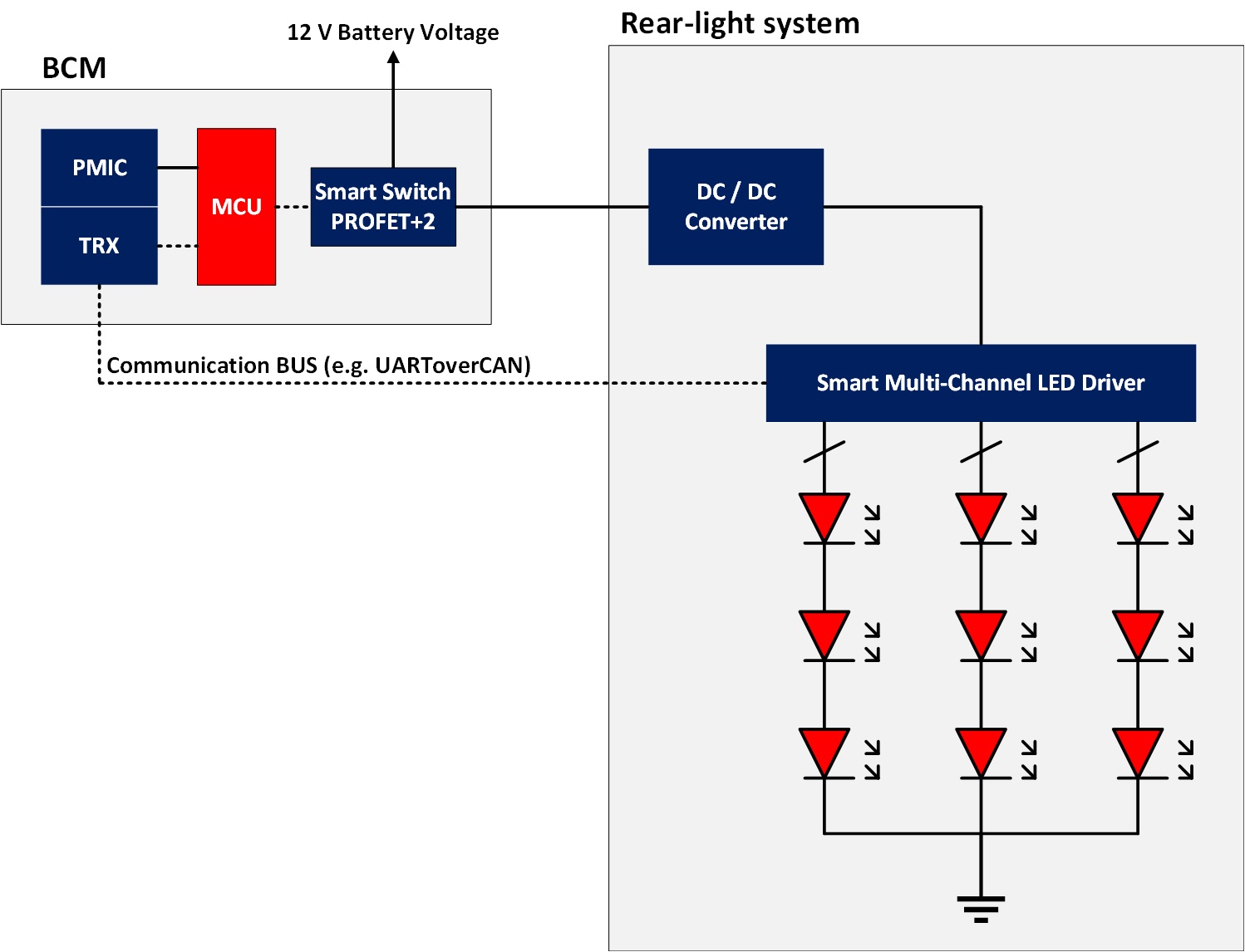
The main reason for changing the standard signal wire architecture comes from the conflict between additional requested features and system cost reduction: Driving many LED strings to perform animated lights would lead to high wire harness length, weight and cost.
In order to overcome this challenge, the LED driver has to become smarter and capable of receiving and answering to BCM messages by communication bus, usually via a CAN transceiver. In this architecture, a single power supply and a single communication bus are able to implement any light function present in the rear light system.
A smart multi-channel driver would be able to drive several LED strings via bus messages, with integrated diagnostic and protection. A significant reduction in LED drivers and wires helps to solve this design challenge with a limited effort in software development.
Rear light systems also have a functional safety rating, up to ASIL B. Several system safety goals have to be met and a specific FIT rate has to be achieved. LED drivers for high-end rear light systems have to be developed according to the ISO26262 standard and advanced diagnostic features are required (e.g. communication bus watchdog or programmable safe state in case of a MCU failure).
Lighting control units for automated driving
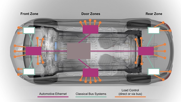
Automated driving level 3 or higher will require additional sensors (e.g. cameras), to be placed in the rear lighting modules. Because of the high computational effort required, new architectures are emerging to distribute the intelligence between the BCM and additional ECUs/LCUs (Electronic or Light Control Units).
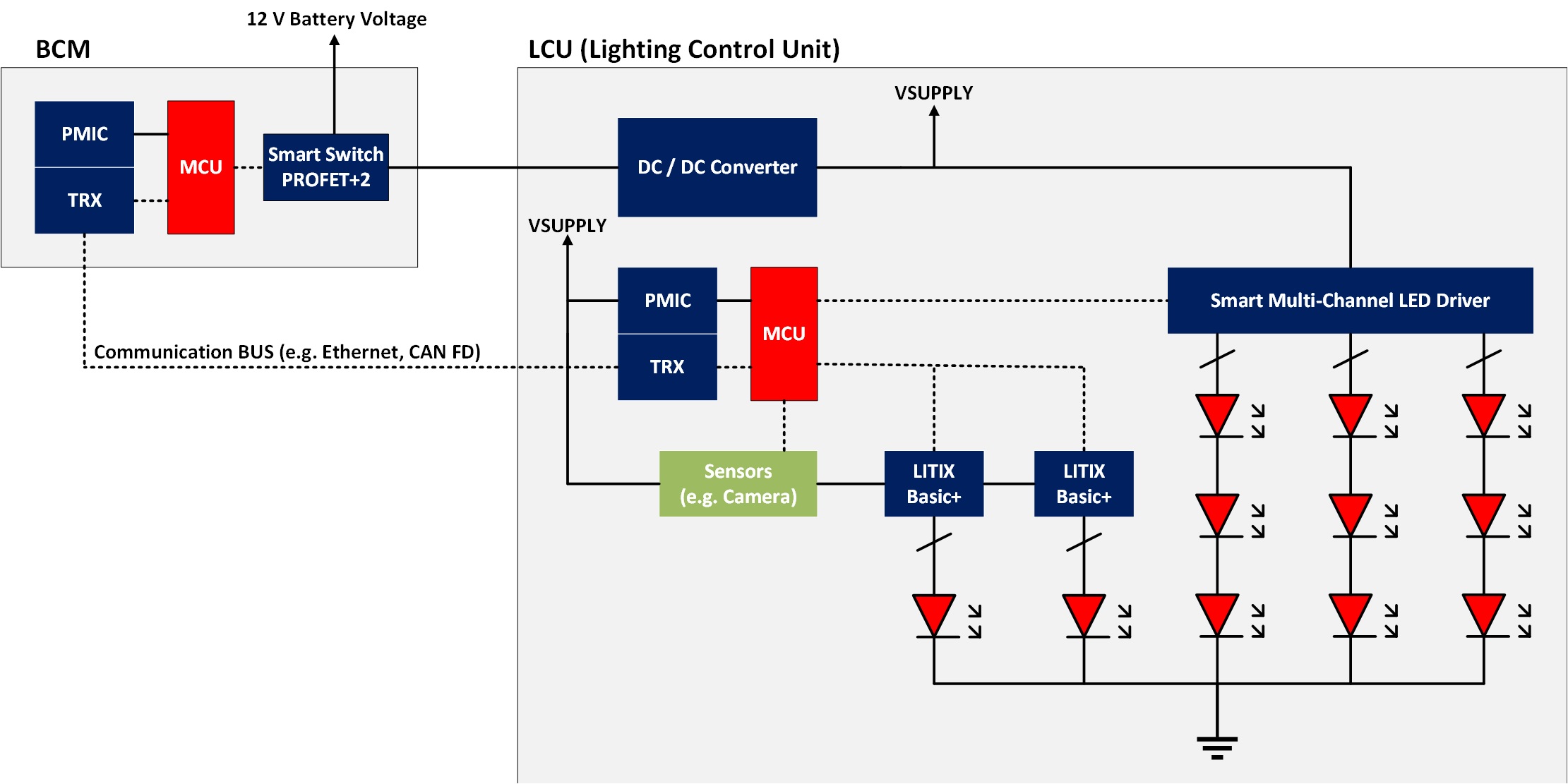
LCUs do not only drive LEDs. They are responsible for an entire car zone or domain functionality and report to the BCM via a central gateway (Fig. 3). Their MCU would also elaborate raw sensor data to be sent to the BCM, and eventually run algorithms according to external conditions to perform adaptive lighting behaviors (e.g. inside a gallery or in fog conditions).
A smart lighting architecture as shown in figure 4 will need several communication buses between the BCM and the LCUs (e.g. Ethernet and CAN) to integrate all required functionalities and to ensure acceptable reaction times under all conditions.
The main challenges in this architecture are:
- Software development and functional safety analysis efforts:Rear light modules with raw sensor data processing responsibility are critical parts for proper car behavior on the road. Safety and security requirements are more stringent and require a joint effort in development for BCM and LCUs, eventually manufactured by different Tier1s or with direct carmakers’ involvement.
- Thermal management, EMC and quiescent current:Housing limited space leads to thermal management challenges. Dissipated power increases because of the MCU and the many devices and loads inside.
For better integration, the MCU power supply could also be an SBC (System Basis Chip, e.g. TLE9471) that takes care of the MCU watchdog for functional safety reasons and CAN communication.
EMC could also be a challenging requirement to meet, because of the limited headroom and several switching devices. In order to optimize EMC performance, spread spectrum frequency modulation is a very important feature, available also in TLS4120 or TLS4125 (DC-DC converters) and in LITIXTM Power TLD5190 (DC-DC controller).
Finally, system total quiescent current value has to be taken into account in the final design: for this reason, one of the most important device features is the SLEEP mode capability to reduce current leakage when the car is parked and to restore full operation only when needed.
Conclusions
Rear Light Systems have come a long way in less than a century. At the beginning of the automotive era, they were not even considered as mandatory in a car and now they play a central role in design and driver experience. Two major technological progresses have helped to drastically change rear light architectures: LEDs and communication protocols. It is now possible to shape the light module in any way the carmaker designers wish and perform eye-catching animations with a limited numbers of devices to drive many LEDs strings. The job of a rear light system evolved from standard LED driving to complex animations management, and to safety critical and data processing tasks. In any architecture, Infineon is able to address designers’ challenges and meet and exceed current and future requirements, e.g. Smart LED drivers, DC-DC converters or controllers, and SBCs.