


Introduction
The use of electronic controls for engine, transmission, and wheel speed in two- and three-wheeled vehicles is growing, particularly in developing nations. This trend is largely driven by mandates to improve air quality, fuel efficiency, and vehicle safety worldwide.


Control of these systems requires robust magnetic sensors and targets that can operate reliably in harsh environments. A frequent challenge is the presence of common mode noise and stray field interference induced by motors and coils during vehicle operation. Gear wear, target damage,and the introduction of ferrous debris to the target can result in a reduction or loss of control signals.
Two common sensor types used in vehicle control are single and differential element Hall effect sensors. While single Hall effect sensors can be used, differential Hall effect sensors provide a superior solution to various system reliability challenges:
- Stray fields
- Installation tolerances
- Sudden air gap changes
- Dynamic air gap changes
Single vs. Differential Hall Effect Sensors
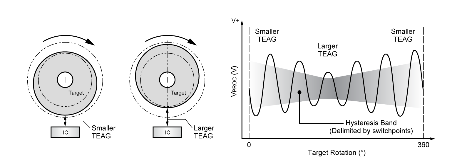
Single Hall effect sensors produce signals that follow the shape of a target tooth/valley, where peak field levels are best over large target features. The signal baseline is dependent on target pitch and magnet design and inherently exhibits a shift or drift over air gap and tooth size changes. The result is a reduction in edge accuracy (Figure 1), which is important for proper engine timing control. To mitigate these effects, a complex magnet system is needed to provide a near-zero baseline field. Another approach is to add sophisticated circuits in the sensor design to minimize and correct for shift or drift.
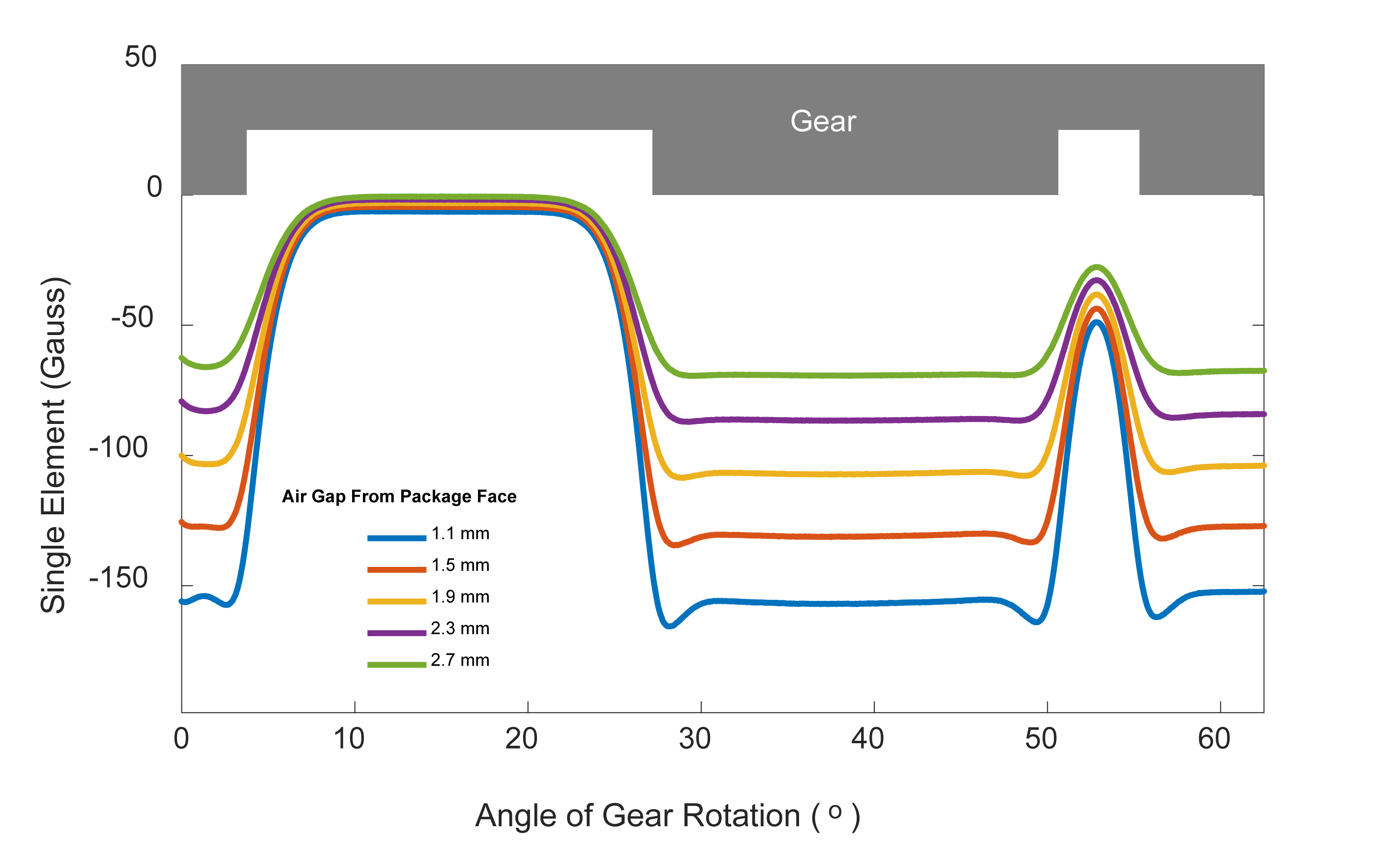
Single Hall effect sensors detect large target features. Notice the offset shift over the narrow target features.
In some basic two- and three-wheeled vehicles, these sensors are successfully used in rudimentary engine or transmission control systems, but the growing trend is toward models with increased vehicle electrification, including engine timing and transmission control. In these applications, single Hall effect sensors often lack the stray field immunity and noise rejection to meet newer model requirements.
Differential Hall effect sensors provide signals that are edge sensing over a target tooth/valley. The signal shape is roughly sinusoidal with up to two times the peak-to-peak magnetic field (Figure 2).
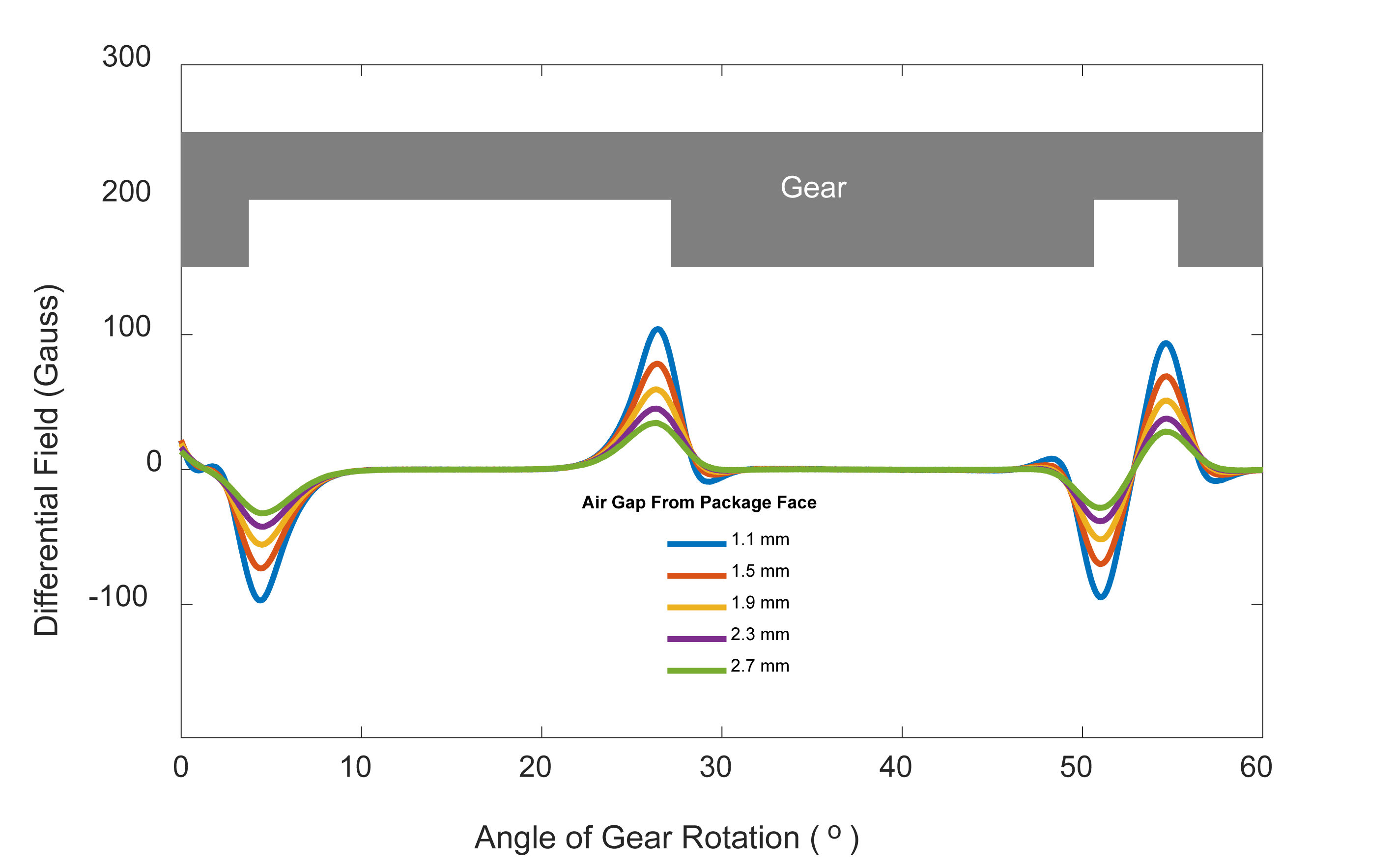
Differential Hall effect sensors detect target edges. No offset shift over the target features.
The differential signal is symmetric about zero gauss since any baseline shift is eliminated through subtraction.As a result, the differential magnet system can be a simple magnet with a high common field. This aids in improving overall air gap performance compared to single Hall effect sensors.
Differential Hall effect sensors and their associated signal processing circuits provide excellent immunity and common mode rejection of noise and stray fields. Baseline drift due to installation tolerance or air gap is reduced by subtraction and offset reducing circuits. Combined, these deliver the performance and reliability needed in vehicles with increased electrification and complex engine timing and transmission controls.Additionally, the edge detection capability of these sensors makes them usable over a wide range of target geometries, particularly fine pitch targets found in most two-wheeled vehicle applications.
Immunity to Stray Fields
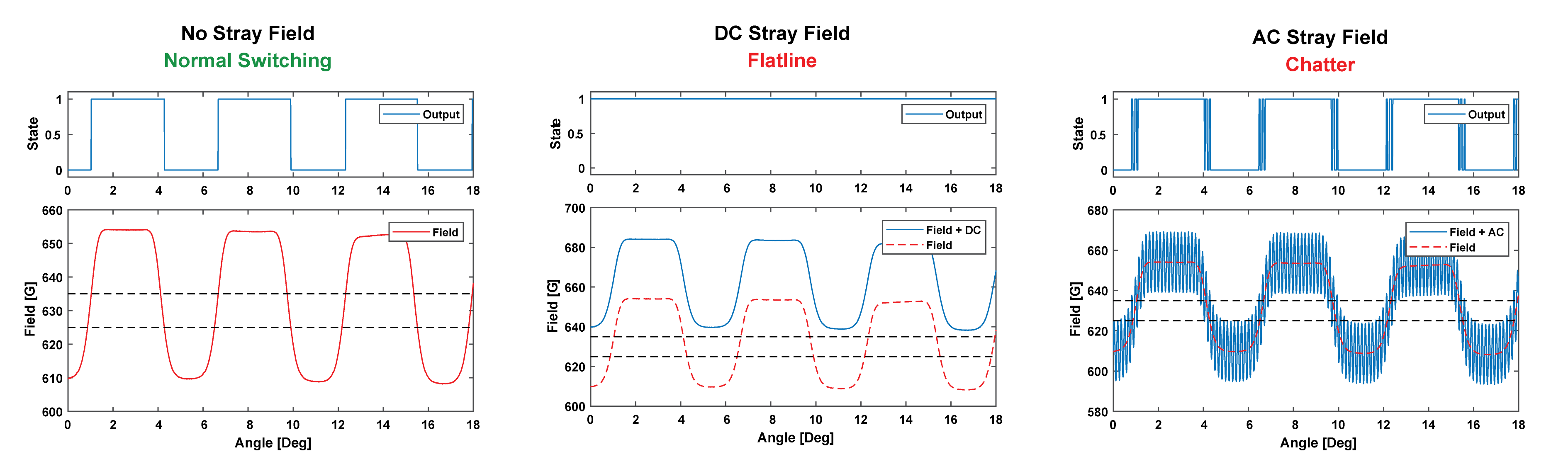
AC and DC generated stray magnetic fields that exist in vehicle power train and control systems are a challenge for speed or direction sensing applications. Single Hall effect sensors are not able to compensate or reject DC and AC stray fields. In Figure 3, the horizontal dash lines show the device switch point levels (625 G and 635 G, for instance) with output switching under a no stray field condition. When a DC stray field is applied, the associated drift causes the magnetic level to shift outside of the switch point thresholds, resulting in no switching and an output flat line. Likewise, if an AC stray field is applied, the noise cannot be adequately rejected and causes the device to “chatter” around the frequency of the applied noise, which is present in the output switching waveform(Figure 3). This added noise can cause system control and timing errors, which can impact vehicle reliability and performance.
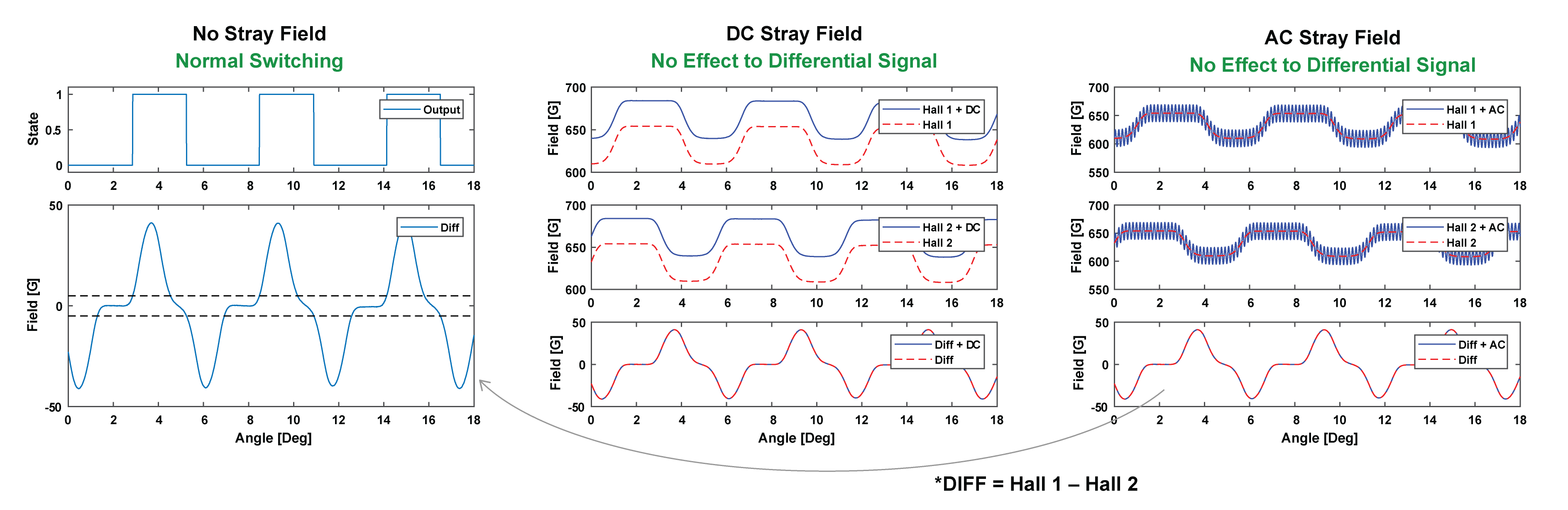
The solution to mitigate the impact of stray magnetic fields and to reduce or eliminate AC and DC interference signals is a differential Hall effect sensor. The differential configuration and circuits cancel common fields applied to the sensor’s Hall effect plates.Allegro’s specific differential architectures further improve sensor performance and stability to external interference.
Figure 4 shows a normal operating condition with comparison to AC and DC stray field disturbance. In the DC stray field example, the top two traces show a DC field applied to each Hall effect element and the subsequent differential output in the lower trace. This shows the effects of subtraction and maintaining the baseline near zero gauss. In the AC stray field example, AC common mode noise is applied to each Hall effect element. The clean differential output (lower trace) is a result of the sensor’s differential input and common mode noise cancellation (rejection). In both stray field cases, the signal integrity and correct output switching is maintained. Additionally,differential Hall effect sensors can also handle the combination of DC and AC at the same time.
Immunity to Installation Tolerances
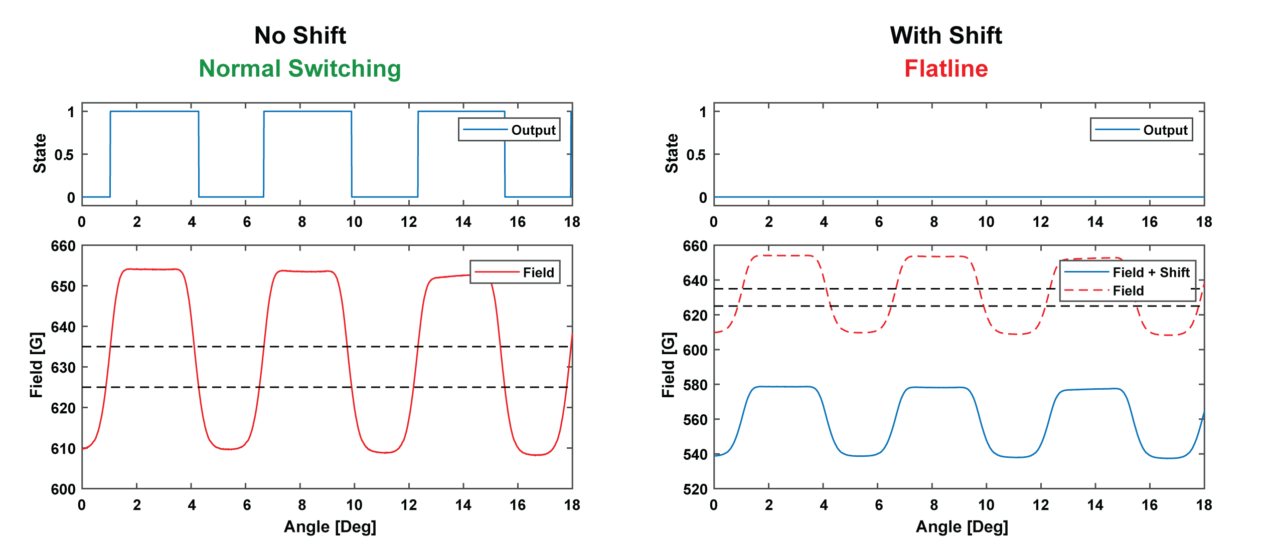
While the operation of a single Hall effect sensor is independent of installation orientation, a change in position can occur after installation. This change in position can result in an offset shift and reduced signal amplitude.Figure 5 shows possible sensor displacement scenarios. These position changes cause an offset from absolute (installed) value, resulting in a DC shift. Figure 6 shows an example of offset leading to a signal level drop below switch thresholds (dashed lines), resulting in no switching and output flat line.
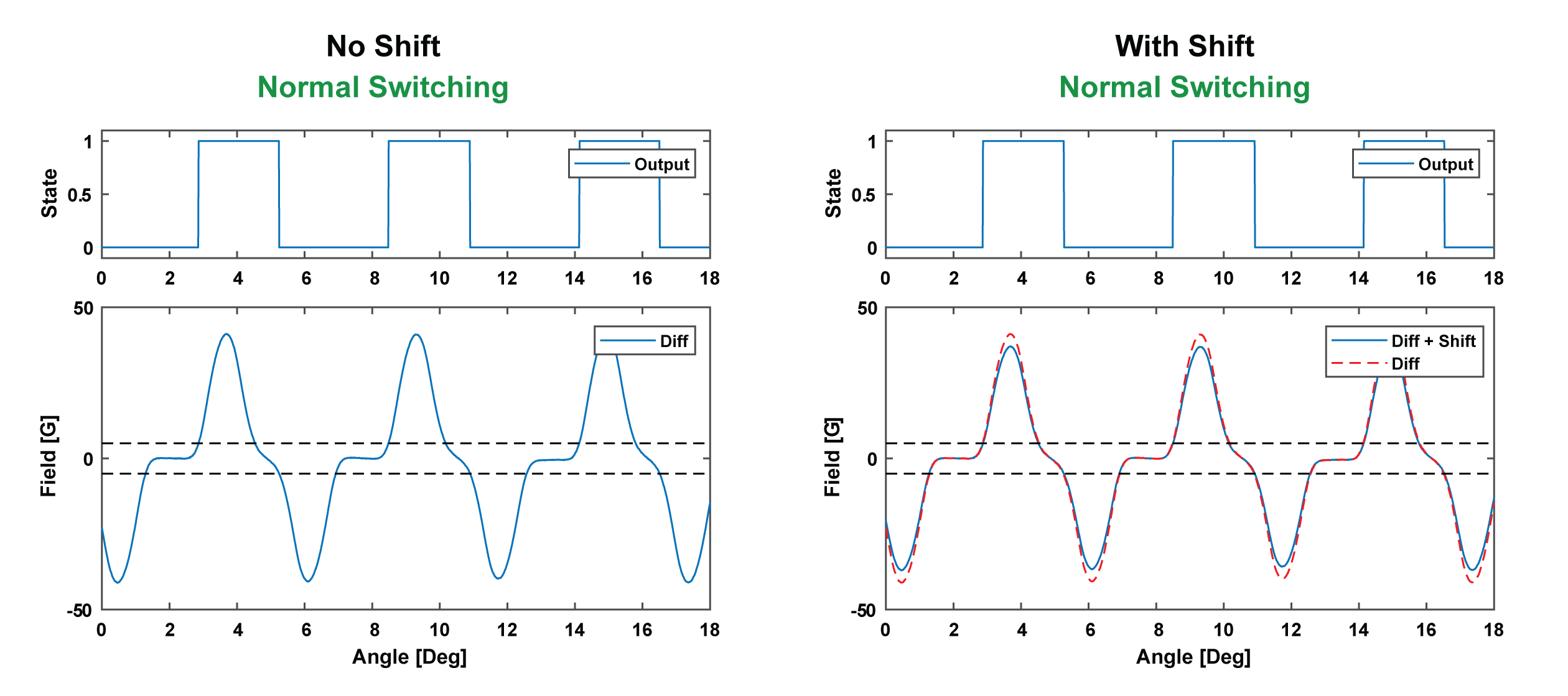
Using a differential element sensor, any offset due to a change in installation position is subtracted and maintains the baseline near zero gauss. This ensures the signal remains within the device switching thresholds, so that normal switching is maintained regardless of the shift in position(Figure 7).
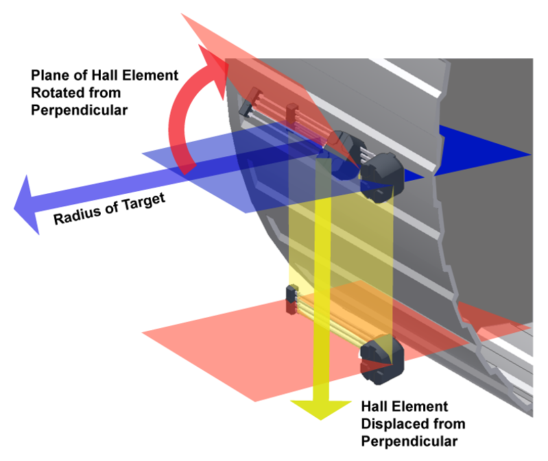
Possible position change scenarios after installation
Immunity to Sudden Air Gap Change
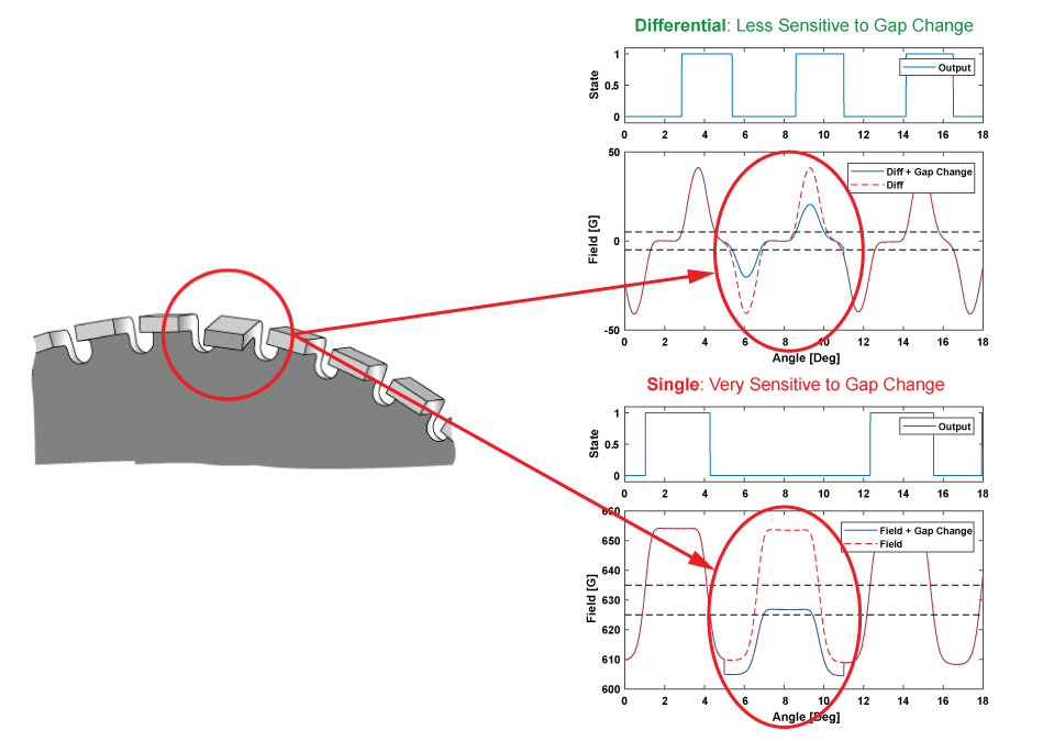
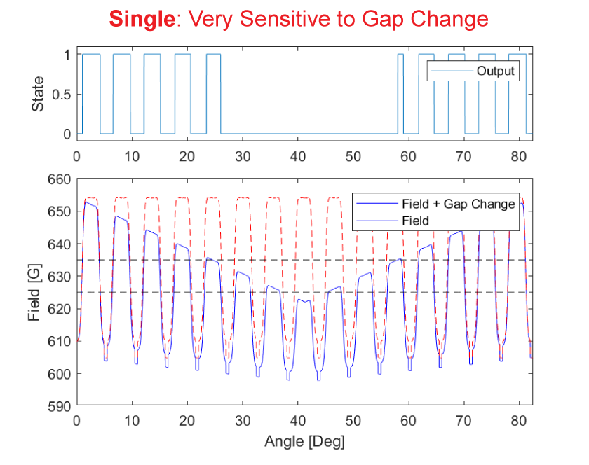
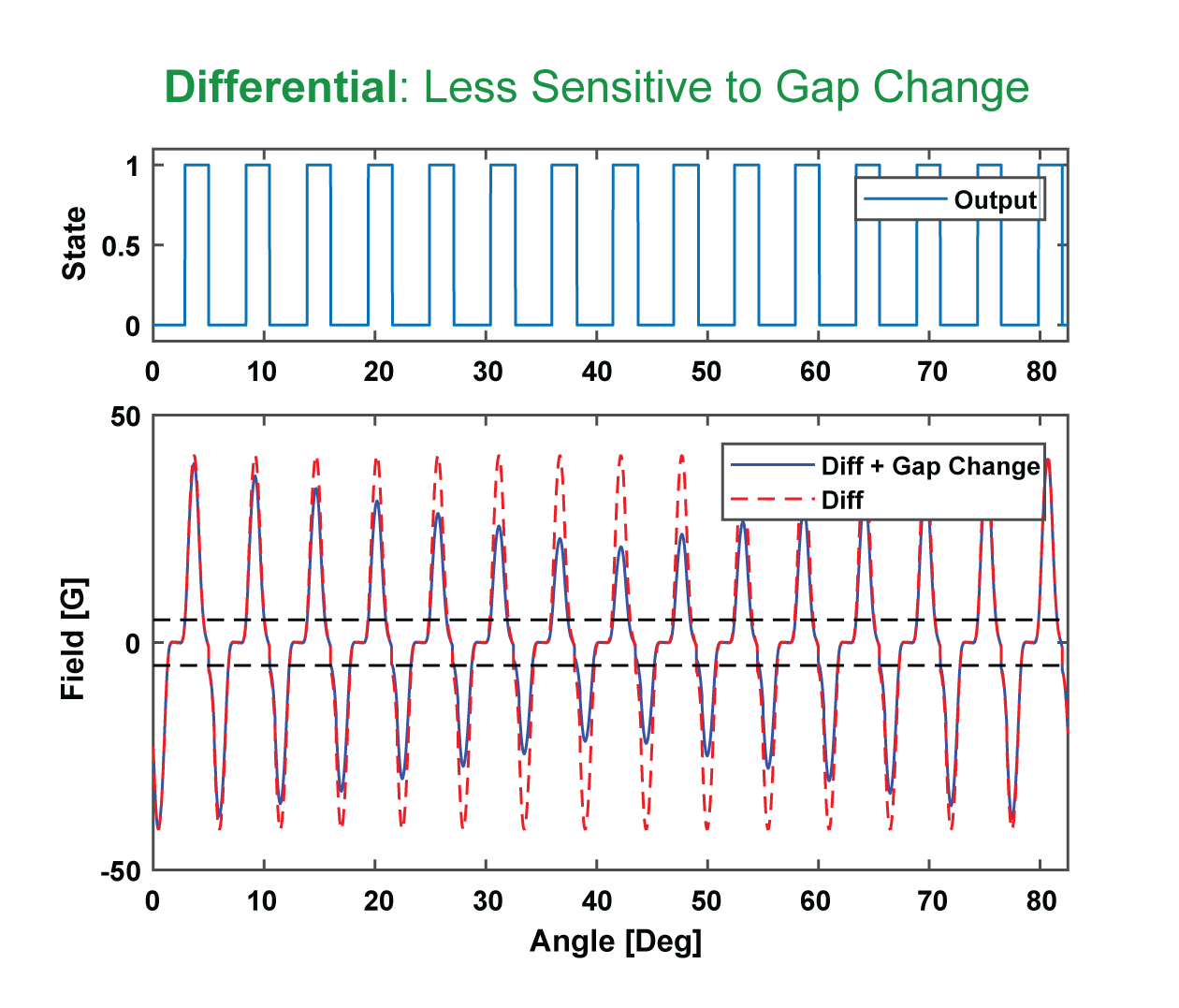
“Sudden” refers to an air gap change from one target feature (tooth and valley) to the next that is not part of the normal features in a given target. For example, sudden air gap changes can be caused by damage from a bent or missing tooth or the introduction of ferrous objects and debris to the target surface.Figure 8 shows an example of a bent tooth target and the associated magnetic field signal generated by single and differential element sensors due to the air gap reduction.
The change in air gap with a single element sensor causes an offset shift and amplitude change outside of the switching thresholds (dashed lines). Once the signal reaches this point, the sensor stops switching and provides an output flat line.
The differential Hall effect sensor subtracts the offset shift and measures the signal amplitude change. The resulting signal maintains the baseline near zero gauss. This ensures the signal remains within the device switching thresholds and the device continues to provide output switching, regardless of the offset shift and air gap reduction.
Immunity to Dynamic Air Gap Change
Dynamic air gap change can occur in applications as a gradual or abrupt change in air gap over target rotation. These discontinuities are usually consistent with every target rotation.The net result is a change in signal amplitude that can occur over multiple target features. Such a condition requires a sensor to properly adapt to the changing signal so that it can continue to switch.
One form of dynamic change in targets for two- and three-wheeled vehicles is target runout or wobble. Runout is a change in air gap that is consistent with every revolution of the target and occurs gradually (over many teeth) as shown in Figure 9. Some common causes are off-center shaft position, target eccentricities, damaged/warped target, or mechanical loading on shafts/bearings.
When a runout or wobble event occurs using a single Hall effect sensor, an offset and amplitude change is measured, and the signal can drop below the switch point thresholds and be lost. This leads to missing speed pulses (Figure 10), which can cause system errors or faults.
Differential Hall effect sensors subtract the offset, preventing a baseline shift(Figure 11). This keeps the signal centered within the device switch point thresholds, allowing proper switching to continue despite the signal variation.
Differential Hall effect sensors are less sensitive to air gap change.
Additional approaches to improve signal integrity and system performance
Two- and three-wheeled vehicles will continue to become increasingly electrified. For the safest and most reliable performance of electronic controls for engine, transmission and wheel speed, differential Hall-effect sensors are the superior solution to single Hall-effect sensors.
To further improve signal integrity and system performance, consider:
- Using sensors with package integrated capacitors to improve EMC performance by reducing electrical impedance between the capacitor and device circuitry. This approach also reduces overall system cost by eliminating a secondary printed circuit board (PCB) to house discrete components.
- Using single over-mold IC and magnet packages that incorporate an optimized magnet pellet for ease of manufacturing, consistent performance over temperature and enhanced reliability.
- Using proven peak detecting algorithms that are robust against signal perturbations.