


-Nazzareno Rossetti, Analog and Power Management professional
-Martin Mason, executive director, Core-Signal Chain, Maxim Integrated
Introduction
In medical ultrasound applications, image clarity – or lack thereof – can make the difference between a cardiologist successfully spotting a problematic turbulent blood flow in your heart or missing it altogether. Use of Doppler imaging techniques, which measure blood velocity and direction, is particularly challenging due to the small return signals from blood flow. For the ADC converters in the ultrasound receive signal path, this translates into a requirement for extremely low total harmonic distortion (THD) and high signal-to-noise ratio (SNR).In this article we will discuss the ADC’s performance necessary for this challenging application.


The Ultrasound System
Ultrasound is one of the most widely used technologies in medicine today, with a broad range of applications that include imaging, blood flow measurement, cancerous lesion detection, bone densitometry and catheter guidance.
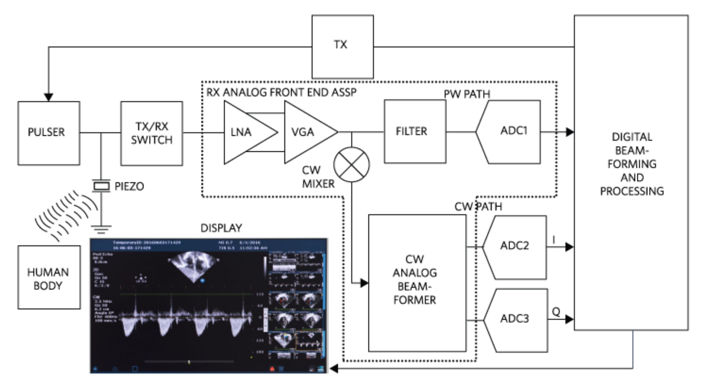
The ultrasound transmitter applies acoustic waves to the body. The ultrasound receiver picks up the echoes reflected from the body structure, typically by means of an array of piezoelectric transducers (Figure 1). The target is identified by the characteristic delay of the reflected pulse, with delays corresponding to distance traveled using Pulsed Wave (PW) transmission. In this mode, the VGA output is filtered, digitized, moved along the PW path and sent off for processing. To obtain accurate details of motion in the targeted area- for example, blood velocity in an artery – a continuous wave must be applied using Continuous Wave Doppler (CWD). In CWD mode, the extraction of the velocity and direction of the blood flow from the received Doppler-modulated signal requires a phase and frequency comparison to the transmitted signal. The comparison is performed using In-Phase/Quadrature (I/Q) demodulation. The system is configured so that either the PW path is enabled while the mixer array is powered down (PW mode), or the quadrature mixer array is enabled while the PW path is powered down (CWD mode).
From a partitioning standpoint, the entire PW path is often integrated into an analog front end (AFE) monolithic IC (ASSP). The AFE is tapped at the VGA output by the CW Mixer to produce the I, Q signals. The CW Analog Beamformer collects the I, Q signals from the entire array of transducers, aligns and sums them. The two beamformed signals are each digitized by external precision ADCs (ADC2 and ADC3 in figure 1) for information extraction and display.
The CW ADCs
The CW path’s bandwidth (BW) must be large enough for the expected Doppler shifts (20 kHz shift). With proper oversampling to maintain signal dynamic fidelity, the ADCs will require approximately 50x samplingor 1Msps. High sampling rate and high resolution (# of bits) both contribute to the high SNR required of the ADC. Another important requirement is low total harmonic distortion (THD), a measure of the non-ideality introduced by the ADC gain errors and non-linearity. THD adds up to a technology figure of merit.
Using high quality ADCs with very low THD to digitize the CW path will help resolve minute details and allows display of the image on screen using a larger selection of colors. For example, a 16 bit ADC will be able to support a high resolution color image.
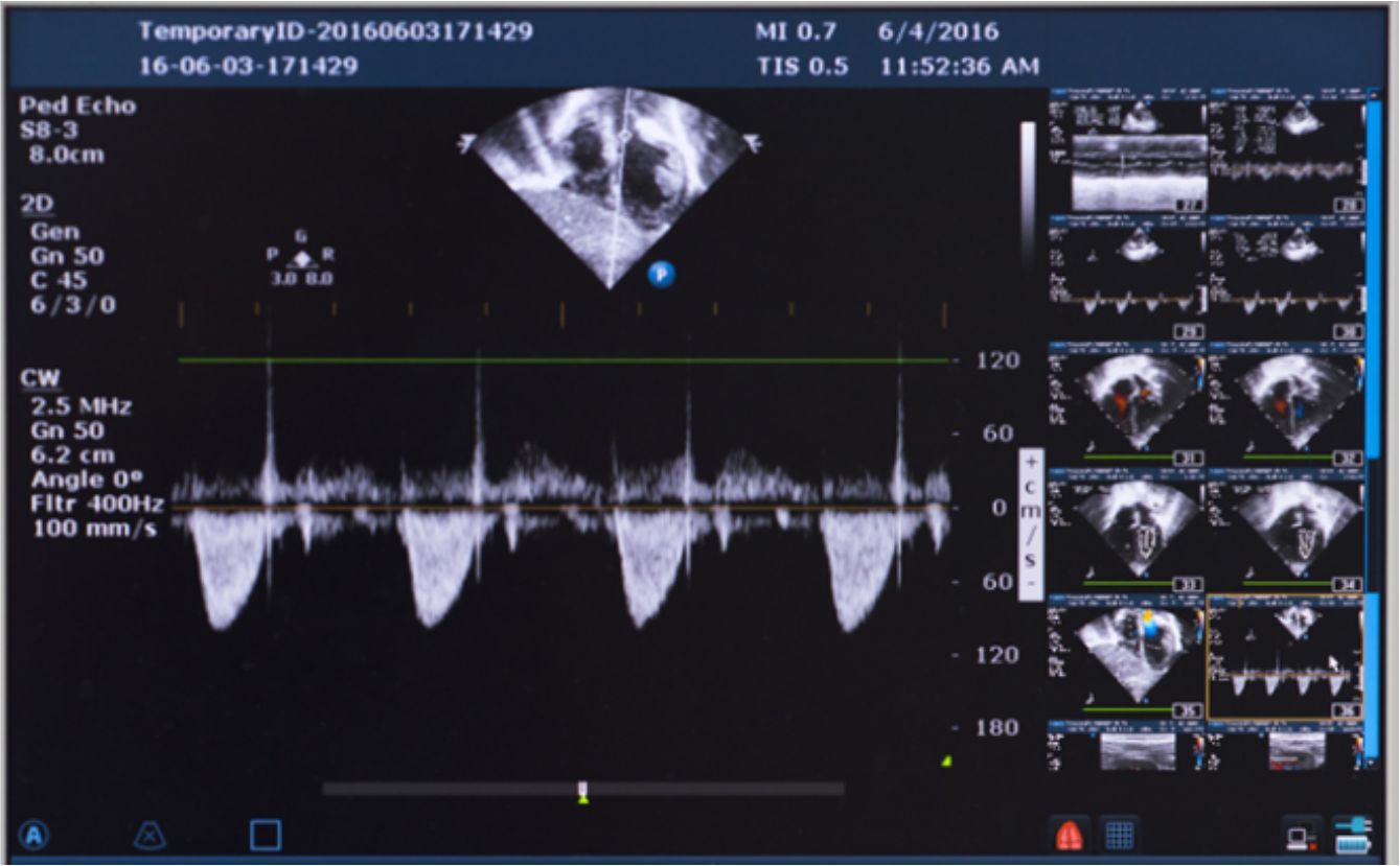
Fig 2 shows B-mode and CF images on the top and side and CW velocity peak detection on the bottom. This is an image taken from a patient with a bad heart valve. The negative cusps on the bottom image indicate the presence of a condition called tricuspid regurgitation.
The Ideal ADC for CW Ultrasound
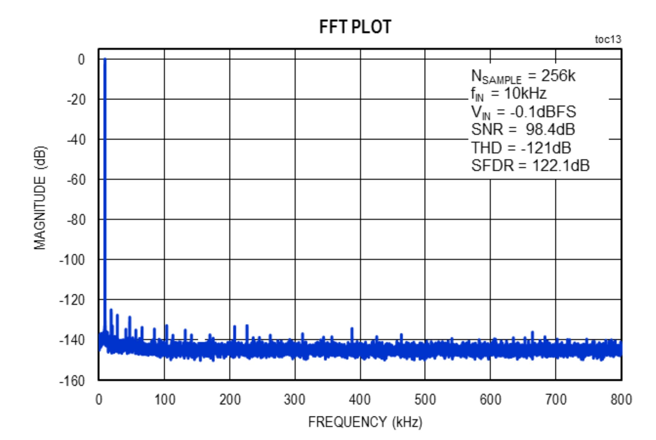
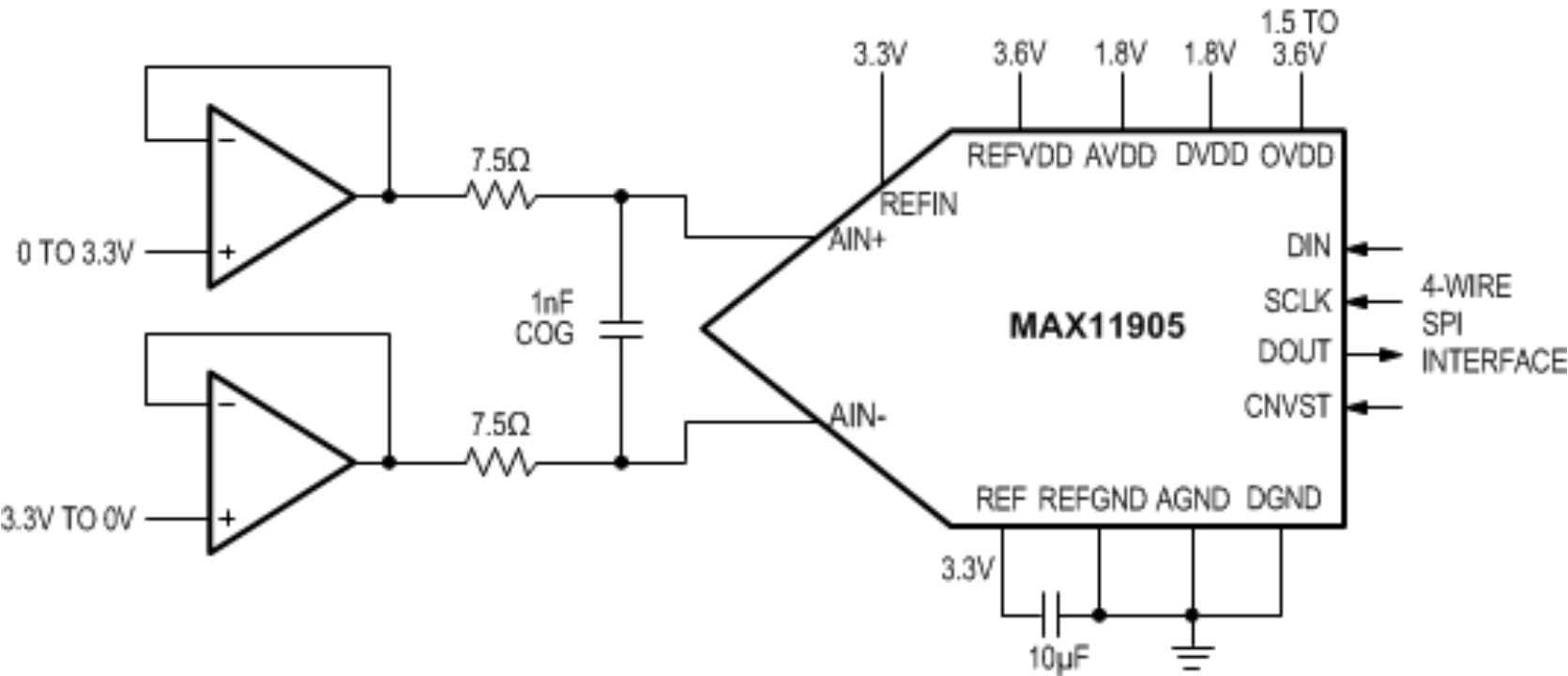
The ideal ADC for this application would combine high resolution and high sampling rate with very low total harmonic distortion and good SNR. The MAX11905 fully differential SAR ADC (Figure 3) is a great fit for this application, as it has a THD of -121dB (as shown in Figure 4), high sampling rate (1.6Mbps), high resolution (20-bit), ultra-low power (8.4mW), and SNR (98.4dB).
For space constrained applications a dual ADC,MAX11960, 20-Bit, 1Msps, Low-Power, Fully Differential SAR ADC is also available.
Conclusion
We have discussed the importance of preserving image clarity in medical ultrasound equipment and how this translates into a demand for extremely low THD, high sampling rate and high resolution ADCs. MAX11905 was provided as an example of a product that meets all the key criteria for demanding ultrasound applications.
About the Authors:
Nazzareno (Reno) Rossetti is a Analog and Power Management professional, a published author and holds several patents in this field.
Martin Mason is executive director for Core-Signal Chain at Maxim Integrated Products. Prior to joining Maxim in 2008 he held product management and engineering positions at Actel, Atmel, Concurrent Logic, and GEC Plessey Semiconductors.