Quartz-based crystal oscillators are the core component responsible for frequency/timing accuracy and performance in nearly all electronic circuits. As such, they are required to be accurate and precise over time. Of course, the “perfect” oscillator only exists in theory, so the problem for designers is the right oscillator to meet the design objectives. This is not an easy task.
Once the performance requirements have been determined for the application, designers need to find the solution with the right balance of performance, cost, stability, size, power, physical structure and drive capabilities for the associated circuitry. To do so, they need to understand oscillator operating principles, key characteristics, and how they have evolved.


This article will provide an overview of crystal oscillator basics before looking at various perspectives related to high-performance crystal oscillator modules. Then, using representative devices from ECS Inc., it will briefly review the basics of these oscillators before identifying the top and second-tier parameters, along with some realistic values for these parameters. It will also show how different units are matched to the need of some typical applications.
How crystal oscillators work
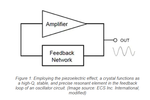
Crystal oscillators provide the clock heartbeat for processors, bit timing for data links, sampling time for data conversions, and the master frequency in tuners and synthesizers. In simplified terms, the quartz element of the crystal oscillator acts as an extremely high-Q resonant element within the feedback network of an oscillator circuit (Figure 1). Due to the importance of crystals and their oscillators, the fundamental physics of the quartz material as well as its electrical and mechanical performance, along with the various oscillator circuits, have been researched and analyzed extensively.
For many years, users would specify the crystal’s frequency and other key characteristics, then provide their own separate oscillator circuit using vacuum tubes (in the early days), then transistors, and finally ICs. This circuit was usually a combination of careful design analysis as well as some “art” and experience-based judgement, as there were many interrelated subtleties. The designer would attempt to balance these factors to match the oscillator performance to the quartz crystal “cut” and characteristics, as well as the application priorities.
Nowadays, such do-it-yourself (DIY) crystal oscillator design efforts are relatively rare because it takes time and effort to get the initial design right. Then there’s the accurate measurement of the performance of an oscillator. This is complex and requires precision instrumentation and a careful setup. Instead, for many applications, designers can purchase a tiny, fully enclosed module which includes both the quartz element as well as the oscillator circuit and its output driver. This obviously reduces the design effort and time, while the user gets a fully characterized unit and a datasheet with guaranteed specifications.
A note about terminology: For historical and other reasons, engineers often use the word “crystal” when then are really talking about the entire crystal oscillator circuit. This is normally not a problem as the intended meaning is understood from the context. However, it can sometimes lead to confusion, as it is still possible to purchase a crystal as a standalone component and then provide separate oscillator circuitry. This article uses the word “oscillator” to refer to the crystal plus its oscillator circuitry as a self-contained module rather than just the oscillator circuit alone.
Characterizing crystal oscillators
As with any component, the crystal oscillator’s performance is initially defined by a set of top-tier parameters. In their general order of importance are:
Operating frequency: This can range from tens of kilohertz (kHz) to hundreds of megahertz (MHz). Oscillators for frequencies above the basic reach of an oscillator, such as into the gigahertz (GHz) range, usually use a phase-lock loop (PLL) as a frequency multiplier to upconvert the fundamental frequency.
Frequency stability: This is the second key performance factor for oscillators. It defines the deviation of output frequency from its original value due to external conditions, and so the smaller this number, the better.
There are many external conditions which affect stability, and many vendors call them out individually so the designer can assess the actual impact in the applications. Among these factors are temperature-related variation with respect to nominal frequency at 25⁰C; other factors include long-term stability due to aging as well as effects of soldering, supply voltage variations, and output load changes. For high-performance units, it is usually characterized in parts per million (ppm) or parts per billion (ppb), with respect to the nominal output frequency.
Phase noise and jitter: These are two perspectives on the same general class of performance. Phase noise characterizes clock noise in the frequency domain, while jitter does so in the time domain (Figure 2).
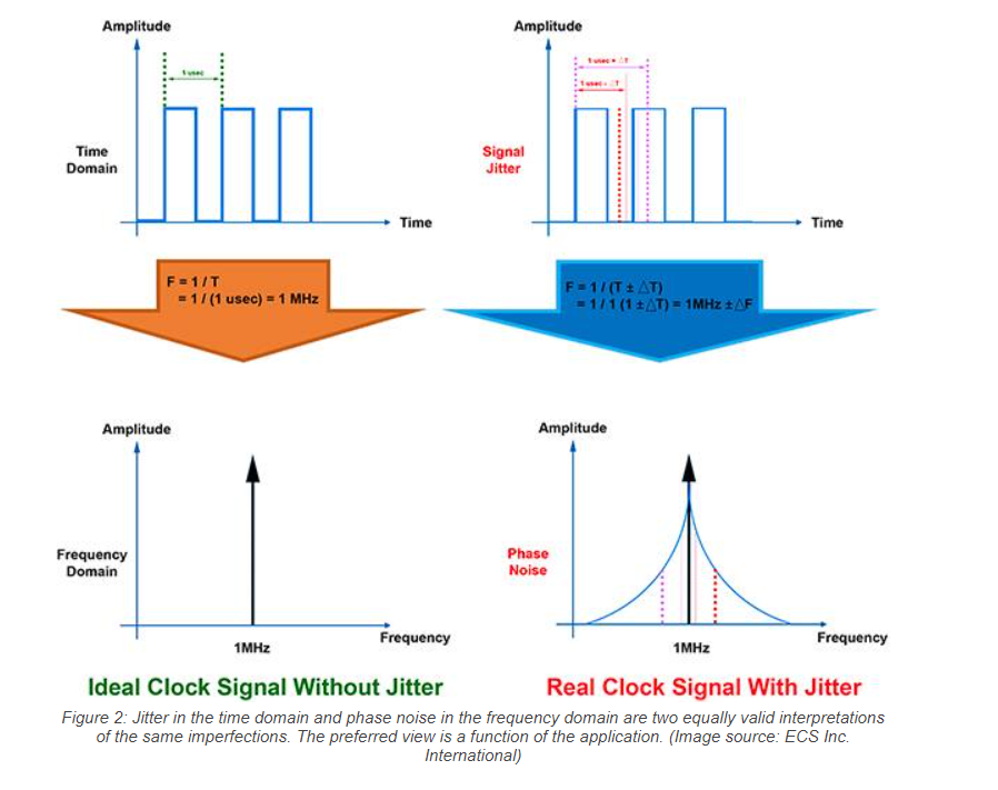
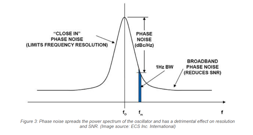
Depending on the application, the designer will be focused on errors primarily as defined in one domain or the other. Phase noise is usually defined as the ratio of the noise in a 1 Hertz (Hz) bandwidth at a specified frequency offset, fm, to the oscillator signal amplitude at frequency fO. Phase noise degrades accuracy, resolution, and the signal-to-noise ratio (SNR) in frequency synthesizers (Figure 3), while jitter causes timing errors and thus, contributes to increased bit error rate (BER) in data links.
Timing jitter causes sampling-time errors in analog/digital conversions and thus, also affects the SNR and subsequent fast Fourier transform (FFT) frequency analysis.
Devices in the MultiVolt family of standard oscillators (MV) from ECS Inc. are available with stabilities as low as ±20 ppm, while their tight stability oscillators (SMV) offer stabilities down to ±5 ppm. For even tighter stability, the MultiVolt TCXOs offer ±2.5 ppm performance with HCMOS outputs and ±0.5 ppm for clipped sine wave outputs (both TCXOs and clipped sine waves are explained further below).
Regardless of domain, phase noise/jitter is an important factor for high-performance designs and must be taken into account in the error budget while keeping the needs of the application in mind. Note that there are many types of jitter, including absolute jitter, cycle-to-cycle jitter, integrated phase jitter, long-term jitter, and period jitter; for phase noise there are different integration ranges and types as well, including white noise and various noise “colors”.
Understanding the specifics of both jitter and phase noise at the oscillator and the impact in the application can often be a challenge. It is difficult to convert a specification from one domain to the other; instead, users should look to the datasheet. It’s also important to understand the legitimate, yet different vendor definitions quantifying performance when accounting for these errors in the overall error budget.
Output signal type and drive: These must be matched to the connected load (Figure 4). The two output drive topologies are single-ended and differential.
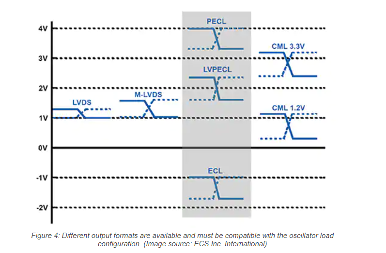
Single-ended oscillators are easier to implement but have more sensitivity to noise and are typically a better fit only up to several hundred megahertz. Among the single-ended output types are:
- TTL (transistor-to-transistor logic): 0.4 to 2.4 volts (rarely used now)
- CMOS (complementary metal oxide semiconductor): 0.5 to 4.5 volts
- HCMOS (high-speed CMOS): 0.5 to 4.5 volts
- LVCMOS (low-voltage CMOS): 0.5 to 4.5 volts
Differential outputs are more difficult to design but provide better performance in high-frequency applications, as any noise common to the differential traces cancels out. This helps maintain oscillator performance as seen by the load circuit. Differential signal types are:
- PECL (positive emitter coupled logic): 3.3 to 4.0 volts
- LVPECL (low-voltage PECL); 1.7 to 2.4 volts
- CML (current-mode logic): 0.4 to 1.2 volts and 2.6 to 3.3 volts
- LVDS (low-voltage differential signaling): 1.0 to 1.4 volts
- HCSL (high-speed current-steering logic): 0.0 to 0.75 volts
The choice of signal type is determined by the application priorities and associated circuitry.
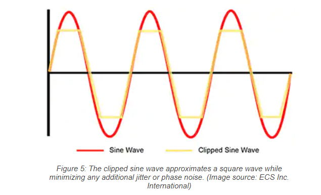
The oscillator output waveform can be a classic single-frequency sine wave or a clipped sine wave (Figure 5). The analog wave is the “cleanest” and least subject to jitter/phase noise, versus using a comparator circuit to transform it into a square wave, as doing so adds jitter/phase noise and thus, degrades it. The clipped sine wave creates a square wave-like output that is compatible with digital loads without sacrificing any of the performance.
Supply voltage and current: These have both decreased to meet the needs of today’s lower voltage and often battery-powered systems. Most MultiVolt series oscillators can operate with supply voltages of 1.8 volts, 2.5 volts, 3.0 volts, and 3.3 volts.
Package size: Just as with operating voltage and current, oscillator packages have also gotten smaller. The industry has some standardized sizes for single-ended devices (which only need four connections), while differential oscillators have six contacts and use the larger packages, with dimensions given here in millimeters (mm):
1612: 1.6 mm × 1.2 mm
2016: 2.0 mm × 1.6 mm
2520: 2.5 mm × 2.0 mm
3225: 3.2 mm × 2.5 mm
5032: 5.0 mm × 3.2 mm
7050: 7.0 mm × 5.0 mm
It’s largely about temperature
The largest external factor affecting and shifting oscillator performance is temperature. Even if the oscillator operating power is low and thus, self-heating is almost negligible, the ambient temperature affects operating frequency as those changes affect mechanical dimensions and stresses of the quartz crystal. It’s important to check the performance of the selected oscillator at the extremes of the expected ranges. These ranges are commonly described as:
Commercial, Automotive Grade 4: 0 to +70°C
Extended Commercial: −20 to +70°C
Industrial, Automotive Grade 3: −40 to +85°C
Extended Industrial, Automotive Grade 2: −40 to +105°C
Automotive Grade 1: −40 to +125°C
Military: −55 to +125°C
Automotive Grade 0: −40 to +150°C
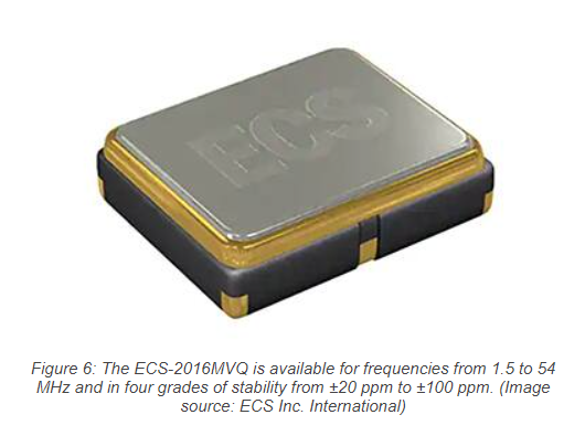
For some designs, it’s not just performance over temperature that is a consideration but also the need to meet other reliability specifications. The ECS-2016MVQ, for example, is a miniature surface-mount MultiVolt HCMOS-output oscillator for 1.7 to 3.6 volts operation (Figure 6). The 2016 (2.0 mm × 1.6 mm, per above) ceramic package measures 0.85 mm high, targets harsher industrial applications, and is AEC-Q200 Qualified (Automotive) for Grade 1 temperature requirements. It is available for frequencies ranging from 1.5 to 54 MHz in four grades of frequency stability, from ±20 ppm to ±100 ppm over -40°C to +85°C; phase jitter is very low at just 1 picosecond (ps), measured from 12 kHz to 5 MHz.
For applications where drift over the operating range is unacceptably high, two advanced oscillator implementations are available: the temperature-compensated crystal oscillator (TCXO) and the oven-controlled crystal oscillator (OCXO). (Note that XTAL is the designation for crystal on many schematics, and “X” is used as an abbreviation for that in the acronym.) A TCXO uses an active circuit to compensate for the change in output frequency due to temperature variation. In contrast, in the OCXO, the crystal oscillator is placed in a thermally insulated oven that is heated and maintained at a constant temperature above maximum ambient temperature (a heating-only oven cannot cool to below ambient).
TCXOs require additional circuitry compared to a basic oscillator but far less power than the OCXO with its oven, which typically requires several watts. In addition, the TCXO is only slightly larger than an uncompensated unit and is much smaller than an OCXO. A TCXO will typically show an improvement in drift between 10 and 40 times that of an uncompensated unit, while an OXCO may show drift performance which is two orders of magnitude improvement in comparison, but with a significant penalty in size and power.
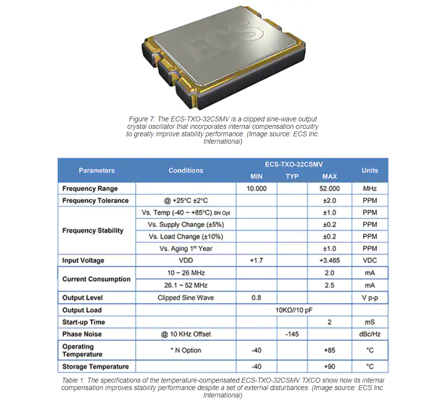
The ECS-TXO-32CSMV is a clipped-sine-wave surface-mount TCXO with MultiVolt capability (1.7 to 3.465 volts supply) for frequencies between 10 and 52 MHz (Figure 7). The 3.2 × 2.5 × 1.2 mm high ceramic package is well-suited to portable and wireless applications where stability is critical. The key specifications show its extremely high stability versus temperature, supply change, load change, and aging along with its modest current requirement of under 2 mA (Table 1).
Low-power operation: often a priority
Despite the trends towards ever-higher frequency processor clocks and data rates, there is still a large need for lower frequency crystal oscillators for timing in extreme low-power applications. For example, the ECS-327MVATX is a miniature surface-mount oscillator operating at a fixed frequency of 32.768 kHz with MultiVolt capability (1.6 to 3.6 volts). With its current requirement of just 200 microamps (µA) and single-ended CMOS output, it’s a good fit for real-time clock (RTC), low-power/portable, industrial, and Internet of Things (IoT) applications. It is offered in 2016 through 7050 package sizes, with frequency stability ranging from a tight ±20 ppm to a somewhat-looser ±100 ppm over the temperature range -40⁰C to +85⁰C, depending on model.
To minimize average power consumption, many oscillators also offer an enable/disable function. For example, the ECS-5032MV is a 125 MHz surface-mount oscillator with MultiVolt operating capability from 1.6 to 3.6 volts and CMOS output, offered in a 5032 ceramic package (Figure 8).
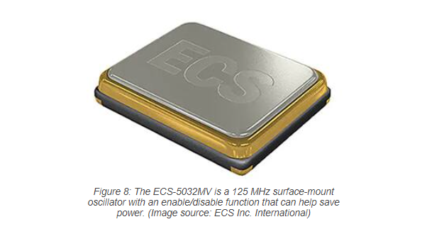
One of its four contacts allows the oscillator to be put into standby mode, reducing required current from the 35 mA active value to only 10 microamperes (µA) standby current. Start-up time is 5 milliseconds (ms) after re-enabling the unit.
Matching specifications to the application
Deciding on a suitable crystal oscillator for an application is, as expected, a balance of specifications, priorities, cost, and their relative weighting. It’s more than the obvious consideration of selecting a unit with the required nominal frequency, frequency stability, jitter/phase noise, and other attributes as a standalone oscillator. Users must also ensure that the output drive of the oscillator is compatible with the associated load and system so that the pairing will not degrade performance. While there are many such considerations, there are some general guidelines:
- An LVDS output requires only a single resistor at the receiver, whereas LVPECL requires termination at both transmitter and receiver.
- LVDS, LVPECL and HCSL have faster transitions than CMOS but will require more power and are best suited for high-frequency designs.
- For lowest power consumption above 150 MHz, CMOS or LVDS are the best choices.
- LVPECL, LVDS, and then CMOS offer the best jitter performance at lower frequencies.
Conclusion
The quartz crystal oscillator is at the heart of many circuits and systems. Ensuring that the performance of this function matches the application requirements requires careful balancing among key parameters, beginning with nominal frequency accuracy, stability versus temperature, and other factors such as jitter and phase noise. It also requires matching the oscillator’s output drive format to the characteristics of the load circuitry. Crystal oscillators in the ECS MultiVolt families offer superior performance with combinations of specifications in complete, easy-to-use modules.