

. With these systems, the battery)
The trend towards electrification in the automotive sector is gathering pace. This is accelerated not only by the limits for exhaust emission values but also by subsidy programs. A core element of these vehicles is the battery charging system, also known as the onboard charger (OBC). With these systems, the battery can be charged at a standard household connection or at a commercial wall box. Depending on the vehicle class, charging systems with up to 22 kW loading power can be installed. This high charging power is required for an acceptable charging time. The use of chargers in the vehicle places very high-quality requirements on suppliers of electronic components. Vishay can draw on a wealth of experience in this area and offer a broad portfolio of suitable components.
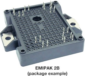
OBCs of up to 22 kW (400 VAC input, 500 VDC output) rely on semiconductor solutions in power modules due to their high power density. By using modules specifically designed for the charger, it is possible to achieve high system efficiency and at the same time high power density. The EMIPAK 2B package is proving to be a very robust and efficient solution in this field. This package has already established itself in a wide variety of applications and configurations. The internal structure of the power modules is specially adapted to the applications and the requirements of the automotive industry. As a result, the power modules can be adapted to each generation of charging systems, and the latest generation of semiconductors can be used in each case. The use of press-fit connections for the electrical contacts makes it very easy and quick to assemble the modules. The direct connection to the liquid cooling system in the vehicle enables a very high power density and optimizes the thermal management of the modules.


In today’s electric vehicles, a high power OBC is required to charge the large-capacity battery pack in a short period of time. 22 kW OBCs work with a 3-phase input voltage in the range of 340 VAC to 480 VAC and provide an output voltage range of 250 V to 500 V, with a maximum current of approximately 50 A. The input stage uses a T-type Vienna rectifier that meets the requirements for harmonic and reactive power, yet allows the charger to operate over a wide input voltage range. The output voltage is controlled by an isolated resonant converter with asynchronous rectification.
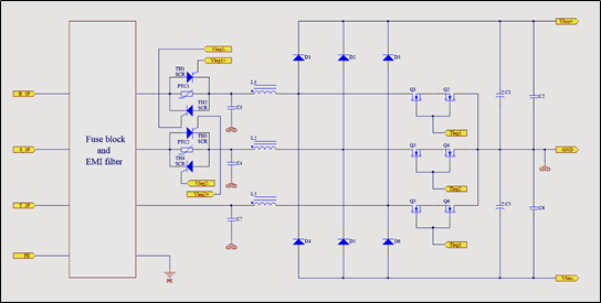
The topology example shown here works with a virtual zero potential, which allows the DC voltage to be divided into two symmetrical stages. With this approach, it is possible to use 650 V silicon MOSFETs for the main DC/DC stage, rather than the costly 1200 V SiC devices required by other topologies.
The use of the T-type Vienna rectifier also implements the required power factor correction (PFC). However, the boost topology used here cannot limit the high inrush current occurring when the charger starts. The DC-Link of the device is stabilized by a relatively large capacitor bank to support both the switching operations of the PFC stage and the DC/DC converter. Depending on the requirements, voltage-resistant aluminium electrolytic or foil capacitors are usually used here. This inrush current must be limited by an active protection circuit to prevent overloading of both the semiconductors and the capacitors. A parallel connection of thyristors and PTC thermistors serves as the required protective circuit in this case. The special behaviour of the thermistors (sharply increasing resistance at high temperature) limits the input current. This ensures that the charging system is switched on safely. When the DC-Link voltage is stable at the desired level, the two thyristors are triggered in order to route the required charging power past the PTC current limiters.
The active rectification of the three-phase current is achieved by the special Vienna topology of diodes and MOSFETs. This circuit corrects the power factor and prevents losses due to reactive power from the capacitive load. In addition, the regulated rectifier can reduce the noise radiating into the network, which simplifies the design of the input filters.
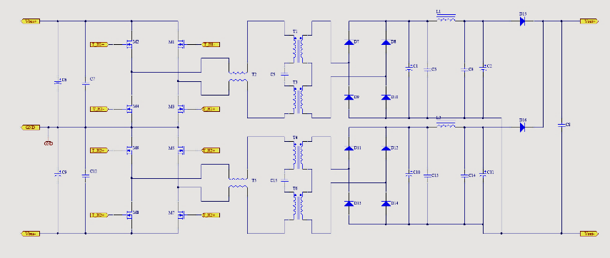
At the centre of the charging system is the isolated DC/DC converter, which is used to set the charging voltage of the high voltage battery. In our example, two resonant converters are used by the Vienna rectifier, respectively, in the positive and negative DC-Link and the virtual zero potential. These are connected in parallel on the output side to achieve the charging power for the battery. The two resonant transformers are driven by a MSOFET H-bridge with a switching frequency in the range of 150 kHz to 250 kHz. The challenge with this topology is to optimize the circuitry of the two resonant transformers for all operating points to minimize interference to the input and output voltages. Along with the transformers, the resonant capacitor is one of the core components of this circuit. In addition to high voltage and current stability, the capacitor must also have very good parameters for the di/dt edge steepness. On the output side, the AC voltage of the transformer is rectified by a diode bridge and stabilized by capacitors. The DC voltage at the output then charges the vehicle battery via the on-board power supply and the battery management system for the next trip with the vehicle.
The semiconductors used in the circuit detail can be integrated very efficiently and in a space-saving manner into the Vishay power modules. The internal design of the modules places great emphasis on minimizing any disturbance variables such as capacitances or inductances. The integration of passive components in the power modules enables further optimization of the design. By using power modules, the efficiency and power density of the charging systems can be further increased to reduce the charging time for electric cars.
For more information, visit www.vishay.com
Authored Article by:
THOMAS LOHRMANN, Manager FAE Automotive Europe, Vishay Intertechnology
STEFAN VOLKMANN, Senior Field Application Engineer, Vishay Intertechnology