


Today, about 7.2 million electric vehicles are on the roads. EVs have the potential to revolutionize energy efficiency, economic growth, and environmental safety. Semiconductors have a big role to play in keeping the electric vehicle revolution on track.
New semiconductor innovations offer the potential for longer and more efficient battery life. Semiconductor chemistries like Gallium Nitride (GaN) and Silicon Carbide (SiC) allow EV batteries to operate at higher voltages than traditional silicon wafers. Semiconductors are also crucial for vehicle safety, intelligence, and efficiency.


With an increase in electric integrations in vehicles, the chip’s content will expand and generate more opportunities for semiconductor players. Let’s take a look at the top automotive power semiconductor companies:
Analog Devices – Using DC Energy Metering applications for EVs
Driven by the development of efficient and economic power conversion technology based on wide band gap semiconductors, such as GaN and SiC devices, many applications now see benefits in switching to DC energy exchange. As a consequence of that, precision DC energy metering is becoming relevant, especially where energy billing is involved.
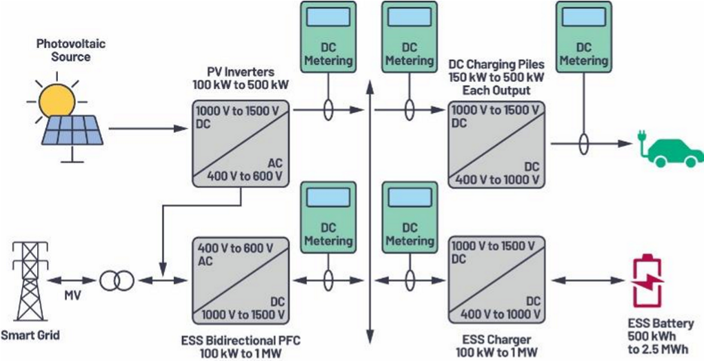
Currently, standard EV chargers are metered on the AC side with the drawback of no measurement of the energy lost in the AC-to-DC conversion and, consequently, billing is inaccurate for the end customer.
While state-of-the-art SiC EV converters can reach efficiency above 97%, there is a clear need to enable accurate billing on the DC side for fast and ultrafast chargers, where energy is transferred in DC when directly connected to the battery of the vehicle.
Silicon Carbide (SiC) Enhances Auxiliary Power in Transportation
Kevin Speer, Sr. Manager, SiC Solutions, Discrete and Power Management, Microchip Technology
With an all-in-one SiC solution incorporating power semiconductor die, digital programmable gate driver, and low-inductance power module, designers can finally achieve disruptive system-level benefits of SiC technology to shrink the size noise, and field failures of Auxiliary Power Units (APUs).
APUs are in a variety of transportation vehicles including:
- Subway and metro trains (light rail)
- Electric buses
- Construction, farming, and mining equipment
- Heavy-duty cargo and delivery vehicles
- Aircraft
All electrified vehicles have two high-power conversion systems: the Traction Power Unit (TPU), which provides vehicle propulsion, and the APU that supplies power for all other on-board loads including lighting, air conditioning, doors and more. Unfortunately, both power units are big, heavy, inefficient and noisy because of the limitations imposed by silicon insulated gate bipolar transistors (IGBTs).
Microchip SiC MOSFETs
Today’s transportation APUs are based on silicon IGBT technology. Compared to IGBTs, SiC Metal Oxide Semiconductor Field-Effect Transistors (MOSFETs) enable the following system-level benefits to APUs:
- Smaller – opens more cabin space for passengers/cargo
- Lighter – extends vehicle range by reducing fixed on-board weight
- More efficient – especially critical for continuously operating APUs
- Quieter – eliminates tiresome electronics whine by switching outside the audible range.
Because the IGBT’s high switching losses generate so much heat, large, expensive heat sinks are required, and a switching frequency limit is imposed (typically 10 kHz). Due to this limitation, the isolation transformer – by far the largest, heaviest part of the APU – cannot be reduced in size or weight. It is also worth mentioning that 10 kHz is very unpleasant to the human ear.
With Microchip’s SiC MOSFETs, switching losses are slashed by up to 80%, and lower conduction losses at light load are optimal for continuously operating APUs. Higher efficiency means smaller, lighter heat sinks. Further, SiC MOSFETs switch with ease beyond the audible range; using 40 kHz as an example, one could reduce the size of the isolation transformer by 75% and simultaneously eliminate the tiresome whine.
Microchip SiC Gate Drivers
While the high switching speeds of SiC MOSFETs are the key to lower switching losses, they also make the system susceptible to EMI failure and voltage spikes. New gate driver technology is required for SiC MOSFETs to optimize the switching transients associated with switching such high levels of power at unprecedented speeds. In addition, the gate driver must quickly detect and respond to short circuit conditions, as SiC MOSFETs have shorter withstand times than most silicon IGBTs. These challenging requirements have motivated the design of Microchip’s AgileSwitchÒ family of software-configurable digital gate drivers.
Unlike conventional turn-off (left), Microchip’s patented technique of Augmented Switching begins with an on-stage voltage (20 V, in this case), moves to a user-programmed intermediate level for a specified dwell time, and finally to the off-state voltage (-5 V, in this case). This allows designers to dial in overshoot voltage and switching losses simply by changing the gate driver settings. In addition, short circuit events are quickly arrested, reducing peak voltage and current by 60% and 10%, respectively.
As a further benefit, the digital programmability of Microchip’s SiC MOSFET gate drivers will accelerate your time to market. With accompanying software, designers can fine-tune their driver settings in seconds with the click of a mouse – as opposed to countless hours in the lab with a soldering iron and bin of gate resistors.
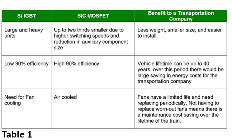
Table 1: Si IGBT vs. SiC MOSFET and benefits to the transportation end-user.
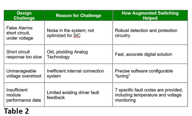
Table 2: Example of how augmented switching resolved customer challenges.
For transportation auxiliary power SiC power applications, Microchip’s AgileSwitch SiC Gate Drivers are a proven solution – with thousands of drivers in service.
Microchip SiC solutions allow APUs to dramatically shrink in size and weight and eliminate noise in ways that are not possible with silicon IGBTs. While these disruptive improvements are possible, care must be taken to ensure complete capitalization of these system-level benefits.
Only Microchip unifies in-house die production with low-inductance power packaging and digital programmable gate drivers so that our clients can make the most efficient, compact, and reliable end products.
Microchip provides unrivaled SiC MOSFET avalanche and short circuit ruggedness alongside total system solutions designed to streamline your SiC development – from benchtop to production.
Essential Power Device for the Heart of Electric Vehicles (xEV) – Automotive IGBT
Kenley, Renesas Electronics
Electrified vehicles (HEVs/EVs) continue to spread and expand while diversifying practical vehicles, SUVs, and sports cars aiming to “respond to the environment and energy conservation” and “improve safety and convenience” as environmental regulations and energy policies for fuel economy and exhaust gas are progressing around the world.
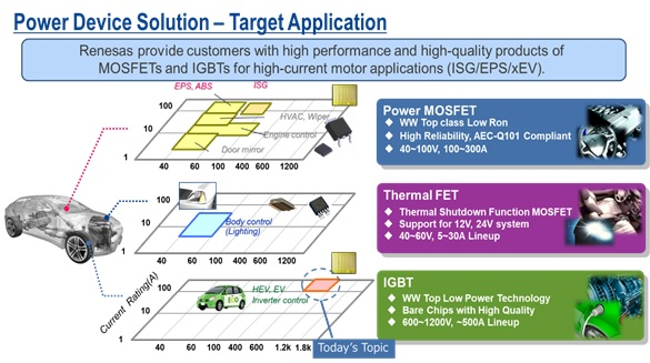
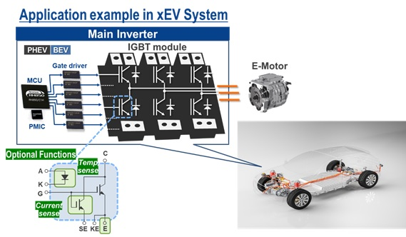
IGBTs are used in the inverter of the powertrain, which is the heart of xEV. However, IGBTs are provided in the form of wafers or chips, so the products embedded in power modules are not usually noticeable. As the demand for xEVs has increased, IGBTs’ adoption record has grown, and in fact, many xEVs equipped with Renesas IGBTs are running around the city. Let me share the 3 key features of our automotive IGBT.
Feature 1: Wide range of voltage class line-ups
The inverter voltage of a typical xEV is around 400, and the IGBTs withstand voltage used for xEV is 650V to 750V. Our competitors also have many line-ups for that range. On the other hand, the inverter voltage requirement has been increasing in recent years, and there is a movement to operate at 800V in some high-end models.
By using high voltage, it has advantages such as “reduction of charging time” and “reduction of weight” by using thinner wire because current can be suppressed. Including other factors, the system voltage and the required IGBT withstand voltage will also vary, but high voltages such as 800V may be also be one of the trends in the future.
In response to customer trends and developing products that meet customers’ needs, we are able to rapidly develop and mass-produce 1200V product, which are required for 800V systems.
Feature 2: Providing solution by value-add functions
In the inverter circuit, the IGBT converts DC to AC by on-off operation, but it may also require incorporating a temperature detection diode and a sub-IGBT capable of detecting current into the IGBT chip depending on customers. This allows you to check the temperature directly from the IGBT chip which is conventionally detected by the thermistor inside the power module. In addition, it is also possible to directly detect the overcurrent detected by the DESAT circuit with a sub-IGBT. These functions are possible with combination of Renesas gate driver IC and the conventional on-off single-function power modules, providing the added value of being able to provide solution for monitoring temperature and current which are well received by customers, especially for automotive applications where safety and reliability are important.
Feature 3: Bare-chip Product Customized Support
We can provide easy-to-use products in response to customers’ requirements such as metallization of the chip surface and delivery form depending on the mounting conditions.
Enhance thermal management in EVs with autonomous cell balancing
Sudhir Nagaraj, Texas Instruments
Cell balancing is important in battery management systems for electric vehicles (EVs) because it helps extend vehicle driving ranges and ensure safe EV battery operation. Cell balancing is also required in order to correct imbalances in the battery itself. All batteries, including those found in EVs, experience unbalancing over time caused by mismatches during manufacturing processes or mismatches in operating conditions, leading to unequal aging between the cells.
A battery can only deliver a charge until its weakest cell has discharged completely, even though other cells may have plenty of charge left. Balancing the cells thus increases battery life by maximizing the capacity of the battery pack and ensuring that all of its energy is available, which in the case of an EV battery extends the driving range. Apart from maximizing battery capacity, cell balancing also ensures safe operation of the battery by preventing cell overcharge and over discharge, both of which can lead to accelerated cell degradation and create potentially hazardous operating scenarios.
How cell balancing works
There are two common approaches to cell balancing: active cell balancing and passive cell balancing. Active cell balancing redistributes the charge from a cell, using DC/DC converters to deliver higher capacity to cells with lower capacity. Today, cell manufacturing and sorting have improved significantly to provide cells with very low mismatch within a battery pack. Thus, it is possible to avoid balancing large mismatches in cells at the onset of operation with a large cell-balancing current. Frequent cell balancing with smaller balancing currents can manage any mismatches that develop gradually during operation.
Passive balancing removes charge from cells with more capacity, typically through thermal dissipation, until all cells have the same amount of charge. The key distinction between passive balancing and active balancing is that passive balancing does not distribute energy but rather dissipates energy until all cells with a higher initial charge finally match the cell that had the lowest charge. Passive balancing is a more popular approach given its simplicity and lower cost.
Cell capacity is often denoted by state of charge to explain the level of charge a battery has relative to its capacity. Figure 1 illustrates the differences in cell balancing types.
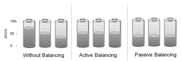
Figure 1: Battery state of charge in various balancing modes
Passive cell balancing in EV batteries
Passive balancing removes charge from an overcharged cell by switching in a resistor in parallel to the cell and dissipating energy into that resistor. This energy dissipation results in heat in the cells as well as the switches and resistor used for dissipation. It is vital to maintain the lithium cell temperature as close to room temperature as possible. Failing to do so may lead to thermal runaway, when the rate of internal heat generation exceeds the rate at which the heat can be released.
Lithium cells degrade at a faster rate at elevated temperatures, caused by structural changes and the formation of surface film at the electrodes. Additionally, excessive heat build-up could damage cell-balancing switches and resistors. A typical EV has large number of cells and cell-balancing switches and resistors that are often packed in close proximity, which makes managing the thermal dissipation in a battery and its battery management system during passive balancing a necessity.
Improving EV battery safety with TI battery monitors and balancers
TI’s BQ79616-Q1 performs passive cell balancing by using switches internal to the device. There is thermal dissipation inside of the BQ79616-Q1 during cell balancing because of these switches. Hotspots are on the printed circuit board (PCB) on the device and the balancing resistors. The BQ79616-Q1 provides two thermal management functions to avoid overheating the die and oversee the PCB temperature.
One thermal management function monitors the die temperature, and the other monitors the thermistor temperature. A high die temperature triggers a fault to the microcontroller (MCU), which can pause cell balancing in order to allow the integrated circuit (IC) temperature to drop. Once the IC temperature drops and the fault is clear, the MCU can command the BQ79616-Q1 to resume cell balancing.
With thermistor monitoring, the BQ79616-Q1 automatically pauses balancing if the temperature exceeds a pause threshold. When the temperature falls below a recovery threshold, balancing resumes automatically. The BQ79616-Q1 pauses and resumes cell balancing in this case without any intervention from the MCU. Figure 2 shows temperature monitoring on the device and by the thermistors.
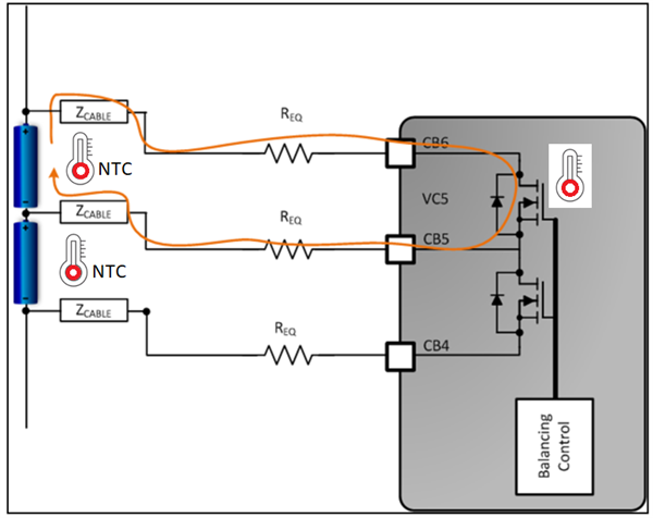
Figure 2: BQ79616-Q1 temperature monitoring locations on the PCB
The cell-balancing pause state also freezes all balancing timers and settings, which do resume once the device is out of the pause state. To manage thermal increases caused by external balancing resistors, the BQ79616-Q1 can pause cell balancing on all channels if any of the active thermistors connected to general-purpose inputs/outputs detect a temperature greater than the set over temperature cell-balancing threshold. Once over temperature cell-balancing detection is triggered, the balancing on all enabled channels will resume once all active thermistors detect a temperature below the established recovery threshold.
Autonomous cell balancing helps maximize battery life, a key benefit for EV batteries. The addition of enhanced IC thermal management and fault indication to the MCU, as found in the BQ79616-Q1, enables quick and safe cell balancing in a cost-optimized manner for longer battery operation between chargers and a longer operational life for the EV battery.
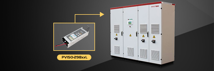
MORNSUN releases 150W 250-1500VDC Input Voltage DC/DC Converter with Smaller Size – PV150-29BxxL Series

Introduction
According to the development of the PV industry, demands of more compact power supply in applications are increasing. MORNSUN newest 150W PV150-29BxxL products can not only be used in PV system, but also suitable for energy storage and charging station, etc.
The products feature ultra-wide input voltage range of 250-1500VDC, wide operating temperature of -40℃ to +70℃, and a compact size of 201x 70x 42mm. Designed to meet CSA-C22.2 No.107.1, EN62109, UL1741 certification standards, which makes them meet the high reliability requirements in applications.
Advantages
- Ultra-wide input voltage range: 200-1500VDC (Transient 1700VDC, duration: 10s)
- Smaller size with optimized design: The dimension is only 201*70*42mm(25.6% reduction), which greatly improves the space utilization for customers.
- High reliability: Isolated voltage of 4000 VAC; b. Multiple protections of output short-circuit, over-current, and over-voltage; c. Meet UL1741, EN62109 certified standards; Operating up to 5000m altitude; Safe and reliable; d. MTBF: MIL-HDBK-217F@25℃≥300,000h
- Wide operating temperature range,low power consumption, high efficiency: Operating temperature range: -40°C to+70°C; b. Efficiency up to 89%
- Excellent EMC performance: EMI: CISPR32/EN55032 CLASS A; b. EMS: CISPR32/EN55032 CLASS A
Applications
It can be widely used in PV industry in combiner box, solar-tracking system, centralized inverter, string inverter, energy storage system, water pumping system, etc.
Features
- Ultra-wide input voltage range: 200-1500VDC (Transient 1700VDC, duration : 10s)
- Operating temperature: -40℃to +70℃
- High isolated voltage of 4000 VAC
- High efficiency, low ripple & noise
- High reliability, long lifespan
- Multiple protections of Input under-voltage, reverse polarity protection, output short-circuit, over-current, and over-voltage
- Operating up to 5000m altitude
- Designed to meet CSA-C22.2 No.107.1, EN62109, UL1741 standards