“The system must accurately determine the deflection amplitude at which the fracture occurs and measure the number of applied cycles until a fatigue break.”
– Balázs Görög, Robert Bosch Kft.


The Challenge:
Creating an instrument that can control and measure the movement of multiple MEMS resonator structures to execute quasi-static and fatigue break tests.
The Solution:
Using the sbRIO-9651 System on Module (SOM) as a compact, small form factor processing unit, and providing it with the necessary digital peripherals and analog front end to create DAQ cards that fit into a measurement rack to execute parallel tests on multiple DUTs for extended durations.
Author(s):
Balázs Görög – Robert Bosch Kft.
László Scherman – Robert Bosch Kft.
Kálmán Benjámin Szőke – Robert Bosch Kft.
Introduction
The Engineering Center Budapest of Robert Bosch Kft. Hungary was founded in 2005 and develops diverse automotive electronic control units and mechanical components, as well as instrument panels and driving assistance systems for cars. The Engineering Sensors for Internal Customers Department (ESI) mainly develops microelectromechanical (MEMS) yaw-rate, acceleration, and pressure sensors for the automotive electronic control units and for consumer products.
There are different processes for manufacturing MEMS structures, which are beyond the scope of this case study. To assure product quality and reliability, we must test the materials and processes and understand the failure mechanisms, preferably in an early design phase. According to a dissertation by Robert Edward Boroch, typical failure mechanisms of MEMS resonator structures are static fracture (under high mechanical load) and fatigue fracture (changes in material on cyclic load over time).

We had to develop a system that could test the above-mentioned failure mechanisms on 20 structures in parallel. It had to perform these tasks:
- find the resonance frequency of the structures
- induce a quasi-static fracture (drive the structures at the eigenfrequency and increase the amplitude rapidly, until break)
- perform a fatigue fracture test (excite the structures at the eigenfrequency for a longer period, until break)
The system must accurately determine the deflection amplitude at which the fracture occurs and measure the number of applied cycles until a fatigue break. We also needed the system to be easily adaptable for similar future tests.
Application Overview
Previous System
The previous system consisted of a PC, signal generators, an oscilloscope, and several measurement cards specially developed for this test. After inserting a sample, we had to manually adjust the measurement cards for each MEMS structure, using trimmer resistors. Each MEMS chip contains multiple structures, so we had to select manually, using jumpers, the structure under test. Once the calibration and the setup was done, the cards were inserted into a rack, where they excited the structures in a closed loop until break. The PC checked each card periodically to detect breaks or changes in the deflection amplitude. The cards were fully analogue, with no built-in intelligence. The calibration of the cards was time consuming and had to be done each time we selected a new structure or inserted a new chip.
We had to develop a system that could select the structure and trim the testing circuit and the measurements at least semiautomatically (preferably automatically).
Measurement Principles
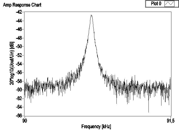
The structures under test include a movable and a fixed part. A voltage applied between the movable and the fixed part of the structure causes a mechanical deflection in the movable part through electrostatic force (driving signal). We can measure the deflection of the movable part by applying a high-frequency signal (measure signal) on the fixed electrodes (with a 180° phase difference between the two), and measuring the resulting current at the moving part. This current is converted to voltage, amplified, high-pass filtered (to remove the driving signal), and demodulated. The resulting signal contains information about the actual position of the structure. We can use it to determine the transfer function of the resonator.
The signal processing consists of a lock-in amplifier using embedded math to get the needed information out of the high environmental noise. There are multiple structures on a single chip, including one with a stopper feature at a known deflection (calibration sample) that we can use to exactly determine the deflection caused by the applied voltage. The other samples have the stopper feature at a higher deflection, allowing a break during the tests.
Hardware Architecture
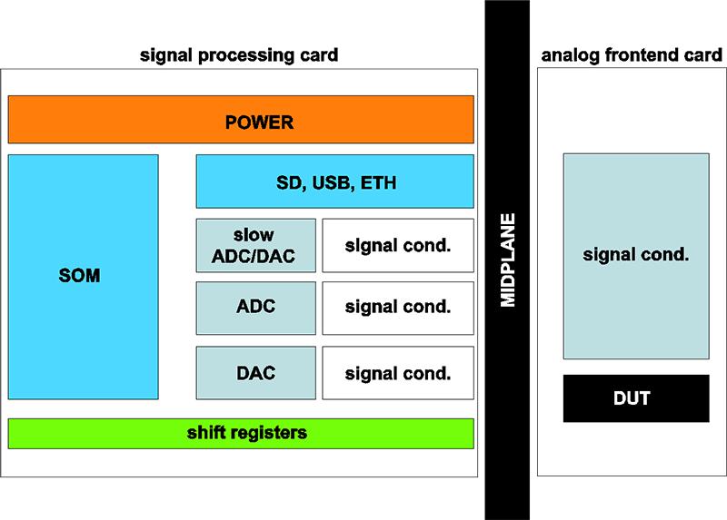
The signal processing cards consist of:
- sbRIO-9651 SOM
- its basic peripherals (Gigabit Ethernet, USB connectors, SD card)
- power supplies
- 2X high-speed (100 MS/s range) A/D converter and its signal conditioning
- a clock generator IC (Si5340) for producing an accurate A/D converter clock
- a dual high-speed (200 MS/s range) D/A converter and its signal conditioning
- 2X low-speed A/D converter and 2X low-speed D/A converter for setting and reading arbitrary parameters
We left more than 40 digital I/O lines unused and routed them to the front end to enable future sophistication of the system.
Challenges
System Architecture
To make the test equipment flexible and reusable, and to detect the fracture time accurately, we opted for a distributed system architecture. This consists of multiple intelligent measurement units operating independently and monitoring the structure continuously. The signal processing task at hand is so specialized that our only option was to build our own signal conditioning circuit. To make the system reusable, we separated the functions into two categories: a general signal digitizer (generator and processing card) and a specialized, task-specific signal conditioning card.
Mechanical Constraints
We needed to fit these cards in a rack, which resulted in non-standard size restrictions. Therefore, we opted for a custom-made signal processing card. To reduce development time, PCB size, and complexity, we decided to use a processor module. There is a big selection of these modules on the market, but we opted for the sbRIO-9651 SOM for multiple reasons. It is compact, includes an FPGA, and we can program it on a high level using LabVIEW. The LabVIEW learning curve is fast, which further increases reusability. The sbRIO-9651 SOM is well documented and has a comprehensive carrier board design guide, which eases hardware development.
The system consists of 20 signal processing cards with SOMs and 20 analog front-end cards responsible for signal conditioning. If built in a rack, the signal processing cards are connected to the front-end cards through a midplane PCB, which carries the power supply. There is a desktop use case, with a single signal processing card directly connected to the analog front end and power supplied externally.
Software Architecture
Software requirements included:
- maintainable with reduced complexity
- signal processing speed should be high and latency low
- must run autonomously, even in case of network loss
- no data loss
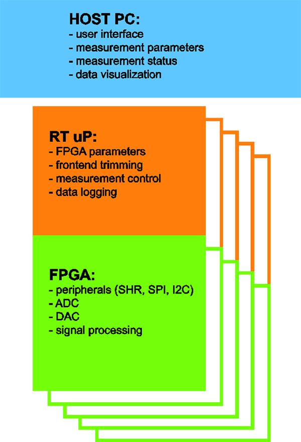
We chose the following software architecture:
- FPGA for signal generation, acquisition, and processing using high-throughput mathematics and handling of peripherals.
- RT controller for downloading FPGA image, parametrizing FPGA functions, executing front-end trimming algorithm, executing measurements, and storing results on an SD card.
- PC software serves as a user interface. User can set up the measurement parameters and the software applies it to each RT controller. It checks the status of each card periodically, collects the measurement data for later evaluation.
Benefits of Using the sbRIO-9651
Using the integrated SOM concept simplified the hardware design task. We reduced development time by avoiding serious hardware errors already in the first prototypes.
Using LabVIEW as a high-level programming language reduced our software development time remarkably. We estimate that it would have taken at least twice as much time to implement the signal processing functions in VHDL. In addition, the use of LabVIEW helps colleagues with minimal FPGA skills to understand and maintain the code in the future.
We could write the software for all three targets (PC, RT controller, and FPGA) in one programming language—LabVIEW. With the traditional solution, we would have had to use at least two programming languages (C and VHDL) to implement the software.
Conclusion
We used the sbRIO-9651 to create a highly customized, yet reusable system for conducting fatigue test measurements on silicon-based MEMS resonator structures. The system is distributed and highly autonomous, which means manual trimming is not necessary. It can be programmed in LabVIEW to accelerate the development and the learning curve. We plan to use it in different applications (testing the resonator structure of novel automotive products, perhaps other data logging applications). Using the sbRIO-9651 greatly reduced development time and PCB complexity, while causing no issues during the development.