Instrumentation allows engineers to see and understand what is going on within different electronic or mechanical processes or systems. These devices obtain, analyze, and present data, permitting engineers to monitor and control machinery and make all necessary corrections. During testing or prototyping, instruments enable circuit improvements so that new and better design can be created.
As highly capable instruments with extensive functionality and usability are needed to meet the design challenges presented by a variety of applications, this article will look at the characteristics these instruments require to meet customer expectations and will then examine important properties of one key design component – the instrumentation amplifier.


Different markets expect different characteristics from an instrument: The military market is reliability-driven; the consumer market is cost-driven; the medical market safety-driven; and the automotive market is a combination of all of the above. That said, however, it is still valid to point out that new instruments designed to meet future requirements generally have to have one or more of the following characteristics:
- Faster speed.One challenge for modern instrumentation is collecting, without loss, a large number of signals while efficiently extracting at high speed the information encoded in these signals. Faster measurement speeds also mean that there must be sufficient room to accumulate the data gathered in memory. One of the most important specifications here is the sampling rate, which is related to the speed at which the device’s ADC takes samples of a signal.
- Smaller size.One of the emerging trends in the instrumentation market is the miniaturization of devices. More and more capabilities are being designed into increasingly smaller designs and without measurement precision penalty. Smaller form factors are in demand for the high-channel-count platforms used for laboratory bench testing. Miniaturization instruments are more easily embedded in large industrial systems. And instruments designed for medical applications must be small to reduce the physical size and weight of a patient-worn device.
- Lower power consumption. Without eliminating functions or increasing amplifier requirements, new devices are expected to reduce power consumption compared to their predecessors.
- Greater immunity to noise and physical or electrical interference.Operational requirements calling for instruments to function in environments with the possibility of noise, vibration, and physical shock all pose challenges to designers. In industrial applications, analog input modules often must acquire and process signals from remote sensors located in harsh environments characterized by extreme temperature and humidity and possibly even corrosive or explosive chemicals. Portable instruments, which now have an almost mandatory requirement of a network-connected user interface (UI), also may well be subjected to a duty cycle that includes temperature extremes as well as moisture and physical stress.
- Increased system reliability and reduced maintenance downtime.System reliability is of primary importance, as the cost of downtime due to equipment failure can be severe. A failed electronics assembly on a drill operating offshore, for example, can take more than a day to retrieve and replace, during which time it holds up the operation of a costly deep-water rig.
- Minimal conversion errors.One example is low quantization noise. The analog input to an ADC is a continuous signal with an infinite number of possible states, whereas its digital output is a discrete function with different states determined by the resolution of the device. In converting from analog to digital, parts of the analog signal that were represented by a different voltage on the input may be represented by the same digital code at the output. As a result, some information is lost and distortion has been introduced into the signal. This is known as quantization noise.
- Higher accuracy and adequate bandwidth.Accuracy is defined as a measure of the capability of an instrument to faithfully indicate the value of a measured signal. Bandwidth describes the frequency range in which the input signal can pass through the analog front end with minimal amplitude loss.
- An efficient cooling design.Heat dissipation elements must not be placed near components sensitive to heat, and airflow must be adequate throughout the device.
Once the operating conditions and performance specifications of an instrument have been determined, the functional components of the device must be identified in blocks. Selection of suitable sensors, signal processing circuits, digital and passive components, and power supplies must be made. Meeting these needs requires a complete BOM of high-performance components such as analog-to-digital converters (ADCs) and digital-to-analog converters (DACs). The former are used to convert analog signals like the output from a temperature transducer, a radio receiver or a video camera into digital signals for processing. Conversely, DACs are used to convert digital signals back to analog signals.
Many applications require substantial signal conditioning to reduce noise, increase dynamic range and compensate for sensor non-linearity before an instrument can effectively and accurately measure the signal. Signal conditioning in analog front ends of medical instruments, for instance, presents the design challenge of detecting small signals in the presence of large differential DC potentials. Consider electrocardiography (ECG): the acquisition and recording of the electrical design activity of the heart (Fig. 1). Each of the cell membranes that form the outer covering of the heart cell has an associated charge that is de-polarized during every heartbeat. These impulses appear as tiny electrical signals on the skin, which can be detected, translated into a waveform, and amplified by the ECG.
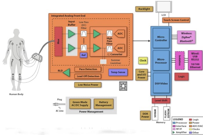
Fig. 1: Block diagram of an ECG device (Source: Texas Instruments)
A companion article, Optimizing Instrumentation Signal Chains for Cost, Performance, examines how designers can build an effective signal chain by balancing specifications of individual components within each stage to meet target performance levels of the signal chain as a whole. In this article, we look at one key element of the process, the instrumentation amplifier (or in-amp), a specialty amplifier type that is generally the first component at the measurement front-end, so its performance is critical to performance of the entire instrument.
In general, signals obtained from sensors have very small amplitudes and must therefore be amplified before processing and display can be accomplished. Simply put, the in-amp’s function is to extract the small signal of interest (a differential design signal riding on top of a large common-mode signal) from, say, pressure or temperature transducers and other signal sources in noisy environments and amplify the difference between two input signal voltages.
In-amps are widely used in medical equipment such as ECG and EEG monitors, blood pressure monitors, and defibrillators. Other examples of instrumentation applications where in-amps may be used include audio (as microphone preamps, for example), high-frequency signal amplification in cable RF systems and high-speed signal conditioning for video imaging. In-amps can also be used for motor monitoring (to monitor and control motor speed, torque, etc.) by measuring the voltages, currents, and phase relationships of a three-phase AC motor.
The main difference between an instrumentation amplifier and an operational amplifier is that an op-amp is an open-loop device, whereas an in-amp comes with a preset internal feedback resistor network that is isolated from its input terminals. As with op-amps, output impedance is very low.
Selecting an in-amp that is a good fit for a particular circuit design requires a clear understanding of its characteristics and how they are portrayed on product datasheets. A few of the properties that define a high-quality in-amp include:
- A high common-mode rejection ratio (CMRR). This is the essential figure of merit for an in-amp. Since an ideal in-amp detects only the difference in voltage between its inputs, any common- mode signals (equal potentials for both inputs) are rejected at the input stage without being amplified. How well, in fact, the in-amp rejects the common-mode signal is measured by the CMRR, which is simply the differential gain of the instrumentation amp divided by the common mode gain. At a minimum, an in-amp’s CMRR should be high over the range of input frequencies that need to be rejected and overall a larger CMRR number is better.
- Low noise.Because it must be able to handle very-low-level input voltages, an in-amp must not add its own noise to that of the signal. Obviously, smaller noise numbers are better. An in-amp’s noise performance typically improves with gain so in- amps should be compared at the appropriate gain.
- Low input offset voltage and offset voltage drift.As with an operational amplifier, an in-amp must have low offset voltage. The voltage offset is a source of error and depends on the topology of the amplifier; it can range from microvolts to millivolts. Amplifiers change behavior over temperature. Even a high-precision design amplifier will be susceptible to temperature drift. Although offset voltage may be negated with external trimming, offset voltage drift cannot be adjusted out. As with initial offset, offset drift has two components, with the input and output section of the in-amp each contributing its portion of the error. As gain is increased, the offset drift of the input stage can become the major source of offset error.
- Low gain error.Typically specified as a maximum percentage, it represents the maximum deviation from the ideal gain equation for a particular amplifier. The gain of an in-amp is either manufacturer-preset or may be set by the user using an external gain resistor or by manipulating internal resistors via some of the in-amp’s pins. Variations in resistor values and temperature gradients among the resistor networks can all contribute to gain error.
- Low nonlinearity.While input offset errors can be corrected, nonlinearity is an inherent performance limitation and cannot be removed by external adjustment. Nonlinearity is normally specified design as a percentage of full scale, where the manufacturer measures the in-amp’s error at the plus and minus full-scale voltage and at zero. Low nonlinearity must be designed in by the manufacturer.
Let’s now consider a couple of real world examples found in the “Newest Products” section of the Mouser website. Analog Devices’ AD8428 in-amp is designed for accurately measuring tiny, high-speed signals. It delivers what is claimed to be industry-leading gain-accuracy (0.2%), noise, and bandwidth. ADI AD8428 (Fig. 2) features fixed gain of 2000 and is one of the industry’s fastest in-amps. The high CMRR (130 dB min) of the AD8428 prevents unwanted signals from corrupting the acquisition data. The part’s pin out is designed to avoid parasitic capacitance mismatches that can degrade CMRR at high frequencies. This ADI device is said to be well suited for use in sensor interface, medical instrumentation, and patient-monitoring applications.
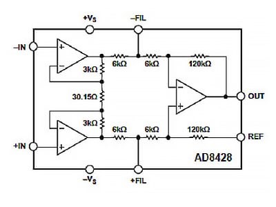
Fig. 2: Functional block for AD8428 (Source: Analog Devices)
Texas Instruments INA826 Precision Instrumentation Amplifiers offer extremely low power consumption and operate over a very wide single or dual supply range. The common-mode rejection ratio exceeds 84 dB across the full input common-mode range from the negative supply all the way up to 1 V of the positive supply. Using a rail-to-rail output, the TI INA826 is well-suited for low-voltage operation from a 2.7-V single supply as well as dual supplies up to ±18 V. TI INA826 Instrumentation Amplifiers are designed for use in a variety of applications, including industrial process controls, circuit breakers, battery tests, and ECG amplifiers.
In summary, to meet the design challenges presented by the different industries in the marketplace, electronic instrumentation and measurement designs are pushing the boundaries of performance, power, and integrated features. This article has presented the characteristics modern instruments require to meet customer expectations and examined important properties of the instrumentation amplifier. Mouser has a large portfolio of in-amps as well as other parts and design resources available to help the engineer tasked with acquiring, monitoring, controlling, or measuring different signals, processes, and protocols.